 微物联研究院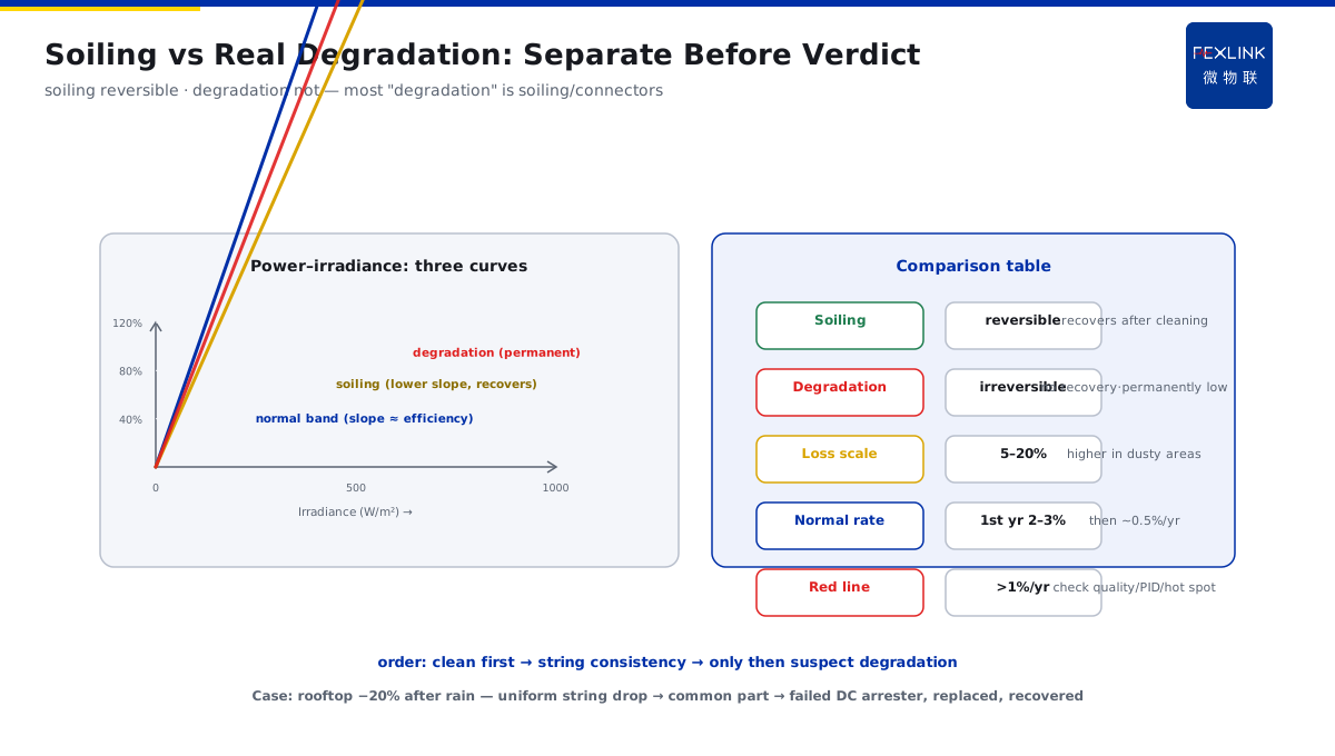
Direct Answer
A PV plant's generation drops — module degradation, soiling, or inverter trouble? The answer: read the data in "three-stage localization" order — first check whether AC power is below neighboring inverters at the same irradiance (macro check), then check whether DC voltage deviates from its normal band (module/MPPT check), finally check whether string voltages are consistent (localize to string/connector). Replace isolated readings with "same-condition lateral comparison," and you can separate modules, MPPT, and inverter within minutes.
At a PV plant, one array generated 12% less than its neighbor; the owner suspected module degradation. In isolation: "DC voltage 620 V, normal band 550–650 V, no problem." But a three-stage check told a different story: at the same irradiance, this inverter's AC power was 12% below the adjacent inverter (same condition, same irradiance, same orientation); then the DC side — not out of range, but string voltages inconsistent: 4 of 16 strings ran 40–60 V below the others. On-site inspection: those 4 strings' MC4 connectors were oxidized and hot, high contact resistance. After replacing the connectors, generation recovered. Verdict: not module degradation — string mismatch caused by connectors. Isolated readings missed it; string comparison nailed it.
Because:
- Lateral first, longitudinal second: isolated readings deceive ("voltage in range" is not "normal"); only comparison at the same irradiance against neighboring inverters/strings means anything;
- DC voltage reads two ways: one, absolute value inside the normal band (which moves with irradiance); two, multi-string consistency (inconsistency = module/connector problem);
- Low AC power + normal DC: points to the inverter (efficiency drop, cooling, IGBT aging);
- Soiling vs degradation: soiling is "power tracks irradiance down, recovers after cleaning"; degradation is "permanent power loss at the same irradiance."
Key insight: generation drop is not "where is it broken," it is "split into three stages first." Modules → MPPT → inverter; each stage has its own signals — exclude stage by stage with comparison data, and you neither blame the modules unfairly nor miss connectors.
At a campus rooftop plant, generation plunged 20% after rain. Three-stage check: AC power low, DC voltage uniformly below the normal band (all strings consistently low). Not a module problem (strings consistent) — pointing to the inverter's MPPT or a common DC-side element. Inspection found the inverter's DC-side surge arrester had failed, dragging the whole DC bus down. After replacement, generation returned. All strings uniformly low = common-part problem; individual strings low = individual-string problem — this rule narrows the search immediately.
1. How the Normal DC Voltage Band Moves with Irradiance
Module DC voltage is not fixed; it moves with irradiance and temperature:
Voltage–irradiance relation:
- Open-circuit voltage Voc: mainly temperature-driven (Voc falls as temperature rises); irradiance matters less;
- Maximum-power-point voltage Vmp: falls as irradiance falls (clearly lower at low irradiance);
- Inverter DC input: operates near the MPPT point, fluctuating with irradiance.
Normal-band judgment:
- The inverter has a DC voltage working range (e.g., 200–1000 V, MPPT 350–800 V);
- But "in range" is not "normal" — compare against the expected value at the same irradiance;
- A uniformly low DC voltage on a cloudy day is normal (e.g., 620 V sunny vs 480 V cloudy) — do not apply sunny standards to cloudy.
Key numbers:
- Full sun: DC voltage near the MPPT upper region (design-dependent);
- Low irradiance: DC voltage may drop to 70–80% of the sunny value;
- Temperature: hot summer modules lower Vmp by 5–10% vs winter (–0.3 to –0.4%/°C temperature coefficient).
Method: log the irradiance–DC voltage relationship to build a normal band; only a deviation from that band (abnormally high or low at the same irradiance) warrants checking.
Key insight: DC voltage must be read "by irradiance." Applying a fixed band to every weather day mislabels normal cloudy-day voltage as a fault and misses real excursions.
2. What Inconsistent String Voltages Mean
String-voltage comparison is the key to localizing "module vs connector":
Mismatch signals:
- Strings under one inverter normally agree closely (deviation <3% or roughly <10 V);
- One string clearly lower (e.g., 5–10% low) → that string has a problem;
- Deviation with overall voltage normal → individual-string problem (module, connector, hot spot, shading);
- All strings uniformly low → common-part problem (DC bus, surge arrester, pre-MPPT).
Common causes:
- Connectors (most common): MC4 oxidation/heat, high contact resistance — voltage drops across the connector, string voltage low, with heat;
- Module hot spot / damage: a module bypassed by its diode, string voltage falls;
- Partial shading: some modules shaded, string current dragged down, MPPT point shifts;
- Aging mismatch: inconsistent degradation within one string.
Judgment rules:
- Deviation 3–10%: watch; check connectors and shading;
- Deviation >10%: clearly abnormal; prioritize hot spots, damaged modules, connectors;
- Combine with IR inspection: connector heat and hot-spot locations appear instantly.
Key insight: string-voltage consistency is the localization microscope. Uniformly low → common; individually low → individual — no need to climb the roof and flip modules blindly.
3. Matching AC Power to Irradiance
"AC power low" must first confirm "low at the same irradiance," to rule out weather:
AC power = f(irradiance, temperature, system efficiency):
- Full sun: AC power approaches capacity × efficiency (e.g., 100 kWp → 90–95 kW);
- Power is roughly linear with irradiance: at 600 W/m² expect about 60% of full-sun power (temperature-adjusted);
- System losses: module degradation, soiling, temperature, cable loss, inverter efficiency — normal total 10–20%.
Same-condition lateral comparison (core method):
- At the same instant and irradiance, compare neighboring inverters/arrays normalized per kWp (or per kW installed);
- Deviation >5–10%: the lower one has a problem;
- The signal is the lateral difference, not the absolute value — a low absolute value may just be bad weather.
AC low + DC normal:
- DC voltage normal, AC low → points to the inverter (efficiency drop, IGBT aging, cooling, fan failure);
- DC normal, AC/DC ratio (inverter efficiency) clearly below nameplate → inverter internals;
- AC low and DC also low → module side (back to string check).
Key insight: AC power must be compared laterally at the same irradiance. Absolute readings are weather-contaminated; lateral comparison cancels weather — the first principle of PV diagnosis.
4. Three-Stage Fault Localization Decision Tree
Exclude "module / MPPT / inverter" stage by stage:
Step 1: macro AC judgment (is it uniformly low?)
- Lateral AC comparison at same irradiance: not low → no problem (or on the AC grid side);
- Clearly low → Step 2.
Step 2: DC voltage judgment (module or inverter?)
- DC normal, strings consistent → AC low = inverter (check efficiency, cooling, IGBT);
- DC uniformly low, strings consistent → common part (DC bus, arrester, pre-MPPT);
- Individual string low → Step 3.
Step 3: string localization (module or connector?)
- Inspect the low string: IR on connectors (heat = contact resistance), hot spots (module damage), shading;
- Connector hot → replace connector (most common, cheapest);
- Module hot spot/damage → replace/repair module;
- Recovers after cleaning → soiling (not degradation).
Decision-tree value: from "whole plant generating low" to "one string's MC4 oxidized" takes three comparison steps — no need to suspect module degradation first.
Key insight: the decision tree's value is the exclusion order. Macro before micro, common before individual — most PV faults are connectors and soiling, not module degradation.
5. Distinguishing Soiling from Real Degradation
The owner's most common question: "Is low generation module degradation?" — first separate soiling from degradation:
Soiling (reversible):
- Feature: generation tracks irradiance down more steeply (lower power–irradiance slope); recovers after rain/cleaning;
- Mechanism: dust blocks light, module current falls, modules themselves fine;
- Judgment: before/after cleaning comparison (recovery = soiling); or power–irradiance scatter leaving the normal band and returning after cleaning.
Real degradation (irreversible):
- Feature: permanent power loss at the same irradiance, no recovery after cleaning;
- Mechanism: module aging (LID light-induced degradation, PID potential-induced degradation, cell degradation);
- Judgment: months of same-irradiance power decline with cleaning ineffective; degradation rate exceeding expectation (first-year 2–3%, then ~0.5%/yr is normal; faster acceleration needs investigation).
Key distinguishing numbers:
- Soiling loss can reach 5–20% (environment-dependent, higher in dusty regions);
- Normal first-year degradation 2–3% (LID), then ~0.5%/yr;
- Annual degradation >1%: abnormal — check module quality, PID, hot spots.
Order: clean first to rule out soiling, then measure string voltage/current consistency, only then suspect degradation — most "degradation" is soiling and connectors.
Key insight: "low generation" does not equal "module degradation." Soiling is the most common and reversible cause — rule it out with cleaning + comparison before reaching for the "degradation" verdict.
6. Product Landing: Online Three-Stage PV Localization
FEXLINK's ESE Power-Quality Monitor / FSE Power-Quality Measuring and Control Device turns "three-stage localization" into online capability:
- Samples inverter AC/DC electrical parameters continuously, auto-building an irradiance–power normal band;
- Same-condition lateral comparison: power vs neighboring inverters at the same irradiance, auto-flagging deviation beyond threshold;
- String-voltage consistency analysis: multi-string deviation over limit auto-localizes "individual string or common part";
- Online inverter-efficiency computation: DC input vs AC output, efficiency drops alert automatically (pointing to IGBT/cooling);
- Before/after-cleaning power comparison logged automatically, separating soiling from real degradation;
- Connected to the Digital Electrical Intelligent Supervision System, generation, irradiance, power, and efficiency share one dashboard for a clear PV-plant health view.
Design principle in one sentence: turn "guessing why generation is low" into "automatic three-stage localization." Modules, MPPT, and inverter each have their own signals — the monitor separates weather from faults for you.
7. Common On-Site Mistakes
- Judging by isolated readings: "DC voltage in range is fine," missing string mismatch. Consequence: connectors oxidize to the point of burning before discovery. Correct: string comparison + lateral comparison.
- Applying sunny standards to cloudy: cloudy low voltage judged a fault. Consequence: wasted trips. Correct: use the irradiance–voltage/power normal band.
- Suspecting module degradation first: not ruling out soiling and connectors. Consequence: cleaning would have recovered it; modules replaced for nothing. Correct: clean first, check strings, only then discuss degradation.
- Watching AC, ignoring DC: replacing the inverter for low AC, missing the failed DC-side arrester. Consequence: inverter replaced for nothing. Correct: DC normal points to the inverter; DC abnormal — check the DC side first.
- Ignoring temperature: summer low generation treated as a fault. Consequence: misjudgment. Correct: normalize by the temperature coefficient (module power temp coefficient ≈ –0.4%/°C) before comparing.
Scope and Limitations
This article discusses three-stage "module/MPPT/inverter" localization for PV plants, applicable to grid-connected systems (mainly string inverters; central inverters need combiner-box data). DC voltage bands, MPPT range, and efficiency follow the inverter nameplate and manufacturer data. Irradiance and temperature normalization require on-site measurements; the values here are engineering references. All cases are anonymized (a certain PV plant / campus rooftop) and do not refer to any specific customer.