 微物联研究院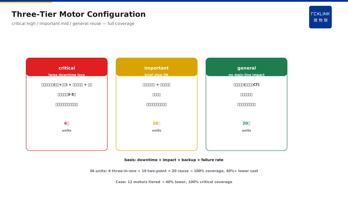
Direct Answer
A workshop has dozens of pump/fan motors and wants unified predictive maintenance. How should the scheme be designed? The answer: tier by criticality — critical motors get temperature + current electrical-signature monitoring; important motors add vibration; general motors get current monitoring only; reuse existing current data for electrical-signature analysis (unbalance, harmonics, load anomalies) to reduce extra sensors; the scheme controls cost with "current data as the mainstay, temperature/vibration as supplementary points."
At a pumping station with 36 motors (6 critical pumps, 10 important pumps, 20 general fans), tiered configuration was applied: critical motors got temperature (bearing/winding) + current electrical signature (reusing existing CT/metering loops); important motors added vibration sensors; general motors only reused current data for electrical-signature analysis. In the first week, the platform found 2 motors with three-phase unbalance (one 8%, one 12%) from current signatures — inspection found loose connections; after repair the currents returned to balance. The core of a motor-fleet predictive-maintenance scheme is "tiered configuration + current as the mainstay": high configuration for critical motors, current-data reuse for general motors — full coverage, controllable cost.
Because:
- With many motors, per-motor sensors are costly: tiered configuration puts investment on critical equipment;
- Current data is a "free sensor": existing CT/metering data enables electrical-signature analysis (unbalance, harmonics, load anomalies) without new hardware;
- Temperature sees thermal faults, vibration sees mechanical faults: only critical motors need these two types of measurement points;
- The ledger and priority are the foundation: classify first (critical/important/general), then configure per tier.
Key insight: motor-fleet predictive maintenance is tiered combination, not "everything on every motor." Current as mainstay + temperature/vibration supplementary points — full coverage, cost down 40%+.
At one plant with 12 motors on a line, the original plan was three-in-one sensors (temperature + vibration + current) on every motor; the tiered plan changed this to 2 critical motors three-in-one, 4 important motors temperature + current, 6 general motors current only. Investment fell 40% with 100% critical-equipment coverage — the value of tiering: spend money on critical equipment, back general equipment with existing data.
1. Three-Tier Configuration by Criticality
Step one: how to classify motors and what each tier gets.
Three tiers:
- Critical motors: large downtime loss (e.g., main process pumps, critical fans);
- Important motors: affects production but can stop briefly (e.g., auxiliary pumps, circulation fans);
- General motors: stopping does not affect the main line (e.g., ventilation fans, small pumps).
Tier configuration:
- Critical: temperature (bearing + winding) + current electrical signature + vibration (three-in-one);
- Important: temperature + current electrical signature (two points);
- General: current electrical signature (reuse existing data).
Classification basis:
- Downtime loss (loss per 1 hour of stoppage);
- Failure impact (whether the main process is affected);
- Backup capability (whether a standby unit exists);
- Historical failure rate (frequent failures → higher priority).
Tier example (36 motors):
- 6 critical: main process pumps, critical fans (production stops immediately);
- 10 important: auxiliary pumps, circulation fans (short switchover to standby);
- 20 general: ventilation fans, small pumps (no main-line impact);
- Configuration comparison: 6 three-in-one / 10 two-point / 20 reuse.
Meaning of tiering:
- Investment matches risk (high for critical, low for general);
- Full coverage (every motor has a monitoring means);
- Clear priority (maintenance resources protect critical first).
Key insight: the three-tier configuration is the investment ruler. Downtime loss + failure impact + backup capability — classification sets configuration, investment lands in the right place.
2. Anomalies Detectable from Current Electrical Signatures
Core: what reused current data can reveal.
Electrical-signature analysis:
- Three-phase unbalance: deviation among phase currents (loose connections, single-phase loads, turn faults);
- Harmonic content: current distortion (VFD influence, harmonic-source equipment);
- Load anomaly: current deviating from historical baseline (mechanical jamming, load change);
- Starting characteristics: starting-current curve (stall, hard start);
- Phase loss/open phase: abrupt current change (supply anomaly).
Reference criteria:
- Three-phase unbalance >10% watch, >20% alarm;
- Current deviation from baseline >15% watch (load anomaly);
- Harmonic distortion over limit (per GB/T 14549 or equipment requirements);
- Abnormal starting current (stall signature).
Detailed electrical-signature criteria:
- Unbalance: >5% record, >10% watch, >20% alarm (loose connection / single-phase load / turn fault);
- Current harmonics: THD >5% watch, >10% alarm (per GB/T 14549 harmonic limits);
- Load deviation: current vs historical baseline ±15% watch, ±25% alarm (jamming / load change);
- Starting current: abnormally long start time (stall / heavy load) → watch;
- Phase loss: a phase current drops to zero → immediate alarm (supply anomaly);
- Trend criterion: any signature continuously worsening (rising slope) → early warning.
Value of current analysis:
- Zero new hardware (reuse existing CT/metering);
- Full electrical-fault coverage (unbalance/harmonics/phase loss);
- Continuous monitoring (trends visible);
- Complementary with temperature/vibration (electrical + thermal + mechanical, three views).
Limitations:
- Current sees "electrical and load," not mechanical wear (bearings, etc.);
- Current cannot see local hotspots (inside windings);
- That is why critical motors get temperature/vibration added.
Key insight: current electrical signature is the free sensor. Unbalance/harmonics/load/starting — reusing existing data gives full electrical-fault coverage.
3. Vibration and Temperature Supplementary Points
Supplementary points for critical motors:
Temperature points:
- Location: bearing (rolling-bearing outer race), winding (end turns / lead exit);
- Role: bearing overheating (lubrication/wear), winding overheating (overload/insulation);
- Reference: bearing temperature, winding-rise thresholds (per motor class);
- Note: direct winding-temperature measurement is difficult; estimation is acceptable (current + rise model).
Vibration points:
- Location: motor end bearings (drive end / non-drive end);
- Role: bearing wear, rotor unbalance, misalignment, looseness;
- Reference: vibration velocity RMS (graded per ISO 10816);
- Reading: vibration trend (slow rise = wear, sudden change = fault).
Supplementary-point principles:
- Temperature mandatory (thermal faults on critical motors);
- Vibration on demand (optional on important, mandatory on critical);
- Few but precise points (3–5 per critical motor).
Meaning of supplementary points:
- Temperature sees thermal faults (local overheating current cannot see);
- Vibration sees mechanical faults (wear current cannot see);
- Critical motors get the full view (electrical + thermal + mechanical).
Key insight: temperature/vibration are the critical motor's supplementary points. Bearing/winding temperature, bearing vibration — electrical + thermal + mechanical, the critical equipment is fully visible.
4. Existing-Data Reuse to Cut Cost
How to control cost:
Reuse sources:
- Existing current transformers (CTs) / metering loops (current data);
- Distribution monitoring systems (existing current/power data);
- VFDs / soft starters (operating-data interfaces);
- Protection relays (protection data).
Reuse methods:
- Data-interface access (Modbus/Ethernet polling);
- Platform analysis (electrical-signature algorithms without new hardware);
- Fusion with supplementary points (current + temperature + vibration combined judgment).
Cost-reduction paths:
- General motors: zero new sensors (current reuse);
- Important motors: temperature only (low cost);
- Critical motors only: full set (investment concentrated on critical).
Cost-comparison example:
- Full configuration: 36 × three-in-one ≈ high investment;
- Tiered: 6 three-in-one + 10 two-point + 20 reuse ≈ 40%+ lower;
- Coverage: critical 100%, important 100%, general 100% (current backup).
Cost-reduction details:
- Shared acquisition: motors in the same cabinet share an acquisition unit (fewer gateways);
- Wireless deployment: supplementary sensors use wireless transmission (less cabling);
- Phased rollout: critical first, then general (staged investment, fast results);
- Maintenance cost: fewer points = less maintenance (lower lifetime cost);
- Metric: investment/coverage ratio (motors covered per 10k investment).
Key insight: data reuse is the key to cost reduction. CT/monitoring/VFD data reuse — current electrical signature with zero new hardware, investment down 40%+.
5. Motor-Fleet Ledger and Priority
Management foundation:
Motor ledger:
- Per-motor information: location, power, purpose, criticality tier;
- Associated equipment: driven load (pump/fan type);
- History: failures, maintenance, replacements;
- Point configuration: which points this motor has.
Priority management:
- Rank by criticality + failure risk (critical + high risk first);
- Monitoring priority (critical motors first);
- Maintenance priority (protect critical when a fault occurs);
- Resource allocation (inspection/maintenance resources tilt to critical).
Ledger value:
- Configuration decisions have a basis (know what each motor needs);
- Fast alarm localization (know which motor an alarm maps to);
- Maintenance history (more accurate trend judgment);
- Scalable replication (new motors configured per tier directly).
Implementation rhythm:
- Step 1: motor survey (ledger + criticality grading);
- Step 2: configuration design (three tiers + point list);
- Step 3: data access (existing CT/monitoring data first);
- Step 4: supplementary-point installation (temperature/vibration on critical/important);
- Step 5: baseline establishment (normal current/temperature/vibration baselines);
- Step 6: trial-run verification (alarm verification + false-alarm-rate assessment);
- Time reference: about 2–4 weeks for 36 motors.
Common-question clarifications:
- "Reusing current" does not mean installing no hardware at all — critical motors still need temperature/vibration points;
- Current-data access requires confirming CT accuracy and data interface (errors affect criteria);
- Vibration-sensor installation location needs qualified personnel (point location affects reading);
- Tiering is not fixed — re-grade after equipment upgrades or line changes;
- Baselines change with season/process and need periodic updates (prevent false alarms).
Key insight: the ledger and priority are the management base. Per-motor tiering + configuration + history — decisions have a basis, alarms localize fast, maintenance has history.
6. Product Landing: Motor-Fleet Predictive-Maintenance Scheme
FEXLINK products bring the motor-fleet predictive-maintenance scheme to the field:
- ESB Three-Phase Unbalance Monitor: current electrical-signature monitoring (unbalance/harmonics/load);
- EST Multi-Channel Temperature Controller: bearing/winding temperature monitoring (critical motors);
- Predictive-Maintenance Scheme: platform ledger management, electrical-signature analysis, trend alerts;
- Vibration monitoring (on demand): critical-motor bearing vibration (third-party sensor access);
- Data reuse: existing CT/metering-loop/VFD data access.
Design principle in one sentence: turn "everything on every motor" into "tiered combination." Current as mainstay + temperature/vibration supplementary points — full motor-fleet coverage, cost down 40%.
7. Common Scheme-Design Mistakes
- Everything on every motor: three-in-one on all without tiering. Consequence: high investment, waste. Correct: three tiers by criticality.
- Ignoring current data: not using existing CTs. Consequence: general motors have no monitoring means. Correct: reuse current for electrical-signature analysis.
- Current only: no temperature/vibration on critical motors. Consequence: thermal/mechanical faults invisible. Correct: add temperature + vibration on critical motors.
- No ledger: motor status unknown. Consequence: configuration has no basis, alarm localization hard. Correct: build the ledger and tier.
- Measure but never judge: data collected but not analyzed. Consequence: anomalies never found. Correct: platform electrical-signature analysis + trend alerts.
Scope and Limitations
This article provides an overall framework for motor-fleet predictive maintenance (three-tier configuration, current electrical-signature analysis, temperature/vibration supplementary points, data reuse, ledger management) for unified multi-motor monitoring projects in workshops/pumping stations/production lines. Tiering criteria should be adjusted with downtime loss, backup capability, and historical failure rates; electrical-signature criteria should be calibrated with motor type and operating conditions; vibration interpretation must be performed per ISO 10816 and other standards by qualified personnel. Online monitoring data is managed uniformly through the platform to form trend alerts. All cases are anonymized (a certain pumping station / a certain plant) and do not refer to any specific customer.