 微物联研究院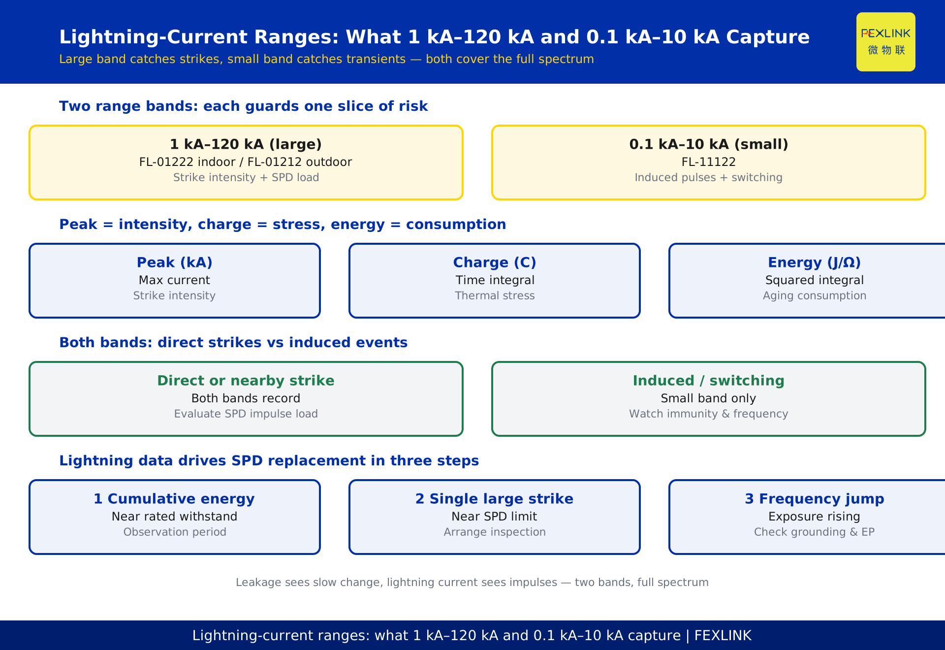
# Lightning-Current Ranges in Practice: What 1 kA–120 kA and 0.1 kA–10 kA Each Capture
Direct Answer
Lightning-current sensors come in two ranges not because "the big one is better" but because each guards one slice of risk: the 1 kA–120 kA band evaluates direct-strike intensity and SPD impulse loading; the 0.1 kA–10 kA band captures small transients and induced pulses; together they cover the full lightning risk spectrum. In the FEXLINK FL-series lightning/transient current monitors, FL-01222 (indoor) / FL-01212 (outdoor) cover 1 kA–120 kA, and FL-11122 covers 0.1 kA–10 kA. Which band you select and how you read the data depends on whether you are asking "how strong was the strike" or "was there a small disturbance."
For electrical engineers and lightning-protection operators, this article clarifies four things: which physical phenomena each band corresponds to; how to read the three parameters of peak, charge, and energy; how to use both bands to distinguish direct strikes from induced events; and how lightning-current data supports SPD replacement decisions.
Why Lightning Current Needs Two Range Bands
Lightning current is not a single magnitude: a direct strike can reach tens of kiloamps, while induced pulses and switching overvoltages may be only a few hundred amps. Using one band for both signals loses on both ends:
- Choose too large a range and small signals lose low-end resolution — a few hundred amps of transient can be eaten by quantization error;
- Choose too small a range and large amplitudes clip — peak and energy data become distorted.
Engineering therefore splits by magnitude: the large band catches "strikes," the small band catches "transients." That is why the FL series separates 1 kA–120 kA from 0.1 kA–10 kA — not specification redundancy but the inherent magnitude difference of what is being monitored.
The 1 kA–120 kA Band: Direct-Strike Intensity and SPD Impulse Loading
The large band (FL-01222 indoor / FL-01212 outdoor) covers 1 kA–120 kA and answers "how strong was this strike":
- Direct-strike amplitude: design lightning-current amplitudes in building protection classifications can reach hundreds of kiloamps; the 120 kA ceiling covers the mainstream magnitude of building protection;
- SPD impulse loading: the larger the amplitude, the more energy the SPD must discharge; one large strike can significantly consume SPD life;
- Strike-intensity statistics: monthly or yearly amplitude distributions reveal regional thunderstorm intensity trends.
The business use of this band is intensity evaluation: judging how large a strike the circuit's SPD has taken and how much tolerance margin remains.
The 0.1 kA–10 kA Band: Small Transients and Induced Pulses
The small band (FL-11122) covers 0.1 kA–10 kA and answers "are there easily missed small disturbances":
- Induced pulses: when lightning strikes nearby, line currents in the hundreds of amps are induced; they do not hit directly but still threaten equipment;
- Switching overvoltages: transients from large-load switching and capacitor bank operations often sit in this band;
- Early disturbances: some equipment degradation first appears as small-current anomalies that only the small band's low-end resolution can see.
The business use of this band is disturbance discovery: bringing "invisible small transients" into the monitoring scope so risk is not masked by peak-only monitoring.
Peak, Charge, Energy: How to Read the Three Parameters
Lightning monitoring records more than one peak value; three parameters each mean something different:
- Peak (kA): the maximum current, reflecting strike intensity, used to judge whether the SPD's impulse withstand is exceeded;
- Charge (C): the time integral of current, reflecting how much charge a strike delivered; more charge means greater thermal stress on the SPD;
- Energy (J/Ω): related to the integral of current squared, reflecting energy released into the circuit — the key input for SPD aging assessment.
Reading rule: peak shows intensity, charge shows stress, energy shows consumption. Looking only at peak misses "moderate amplitude but long duration" high-energy strikes — the ones that consume SPD life most.
Combining Both Bands: Distinguishing Direct Strikes from Induced Events
Reading both bands together answers a key question: was this event a direct strike or induced interference?
- Both bands record: mostly a direct or nearby strike, high intensity, requiring SPD impulse-loading evaluation;
- Only the small band records: mostly induced pulses or switching disturbances, low intensity but possibly frequent, requiring attention to equipment withstand and repeated shocks;
- Both bands record frequently: the circuit's lightning exposure is high; check lightning-protection zones and SPD configuration.
The value of combined reading is graded response: direct strikes focus on SPD life, induced pulses focus on equipment immunity — no one-size-fits-all action.
How Lightning-Current Data Supports SPD Replacement
The end point of lightning-current monitoring is "when to replace the SPD":
- Watch cumulative energy: accumulate the energy of each strike; enter an observation period as it approaches the SPD's rated energy withstand;
- Watch single large strikes: when a single amplitude/energy approaches the SPD limit, arrange inspection even without a failure indication;
- Watch frequency jumps: a sudden rise in monthly strike count means rising exposure on that circuit; check grounding and equipotential bonding in parallel.
This logic turns SPD maintenance from "replace when broken" into "schedule by data," complementing leakage monitoring (which reflects degradation): leakage sees slow change, lightning current sees impulses.
Selection Guide: Which Band My Site Should Focus On
| Site characteristic | Priority | Recommended model |
|---|---|---|
| Main incoming lines, building main distribution, outdoor towers | Direct-strike intensity and SPD impulse loading | FL-01222 (indoor) / FL-01212 (outdoor) 1 kA–120 kA |
| Low-voltage branches, communications, security circuits | Induced pulses and small transients | FL-11122 0.1 kA–10 kA |
| Critical circuits needing full-spectrum coverage | Both bands combined | Large + small bands together |
Selection tip: do not use one band for everything. Use the large band on main incoming lines and the small band on branches and low-voltage systems; for critical circuits that need a complete risk picture, deploy both bands so the data complements each other.
Eight: Three Field Symptoms of a Wrong Range
A wrong range never raises an error, but it shows in the data:
- Clipped peaks: a small range measuring large currents flattens the waveform top, and the peak sits exactly at the range limit — if you see "peak exactly at full scale," suspect the range;
- Low-end dead zone: a large range measuring small signals has big low-end quantization error; small transients appear as "step-like" jumps or vanish entirely — long-absent small disturbances mean insufficient resolution;
- Frequent full-scale hits: repeated full-scale records on a circuit mean exposure is higher than expected — re-check the range selection before deciding to upgrade protection.
Quick check: clipped peaks → check range; lost small events → check resolution; frequent full scale → check exposure. Three signals, three actions — don't misread a range problem as a device problem.
Common Selection and Deployment Mistakes
- Mistake one: bigger range means safer. A large range measuring small signals loses low-end detail, and small disturbances stay absent for long periods. Choose the range by the monitored object, not by the "maximum value";
- Mistake two: install the sensor but never connect the data. Lightning-current monitoring earns its value from statistics and trends. Installing without connecting to the platform is equivalent to not installing — SPD replacement decisions still rely on gut feeling;
- Mistake three: look at the two ranges separately. Direct and induced events can only be told apart by comparing both ranges. Reading a single range mislabels induced pulses as direct strikes and overestimates SPD consumption.
Putting these three mistakes into the acceptance checklist eliminates most of the rework that would otherwise surface later.
Ten: How Lightning-Current and Leakage Monitoring Work Together
Lightning protection and leakage are two different but related risks: lightning current is an external shock, leakage is internal degradation. Used together they answer a more complete question:
- Check leakage after a strike: after a major strike, SPDs may degrade and insulation may be damaged. The lightning-current record triggers a "post-strike special inspection" flow, and leakage monitoring verifies the insulation state;
- When leakage rises, check the environment: a slowly rising leakage on a circuit may be equipment aging — or cumulative insulation damage from repeated strikes. Only by putting the two datasets together can you attribute the cause correctly;
- Merge the ledger: record lightning events and leakage trends in the same equipment ledger, and schedule SPD replacement and insulation maintenance together, so two teams are not managing one device in silos.
The pairing rule: lightning current tells you how hard it was hit; leakage tells you how far it has quietly decayed. One manages shock, the other manages degradation; together they form a complete equipment-health picture. This combined view is exactly what turns reactive repair into scheduled, evidence-based maintenance.
Scope and Limitations
Reading page for KD-0017. The FL-series ranges (FL-01222 indoor / FL-01212 outdoor 1 kA–120 kA, FL-11122 0.1 kA–10 kA) come from the FEXLINK product knowledge base (lightning/transient current monitors) as product-documentation conventions; final values follow the selection manual and datasheet. GB/T 21714 / IEC 62305 are cited as general lightning-protection standard families; specific clauses follow the standard texts. The "design amplitudes up to hundreds of kiloamps" corresponds to conventional lightning-protection design magnitudes and depends on the project's protection classification. The peak/charge/energy reading method and graded-response logic are this article's synthesis for engineering reference. Site-specific lightning-current monitoring configuration should be determined by professional lightning-protection designers.