 微物联研究院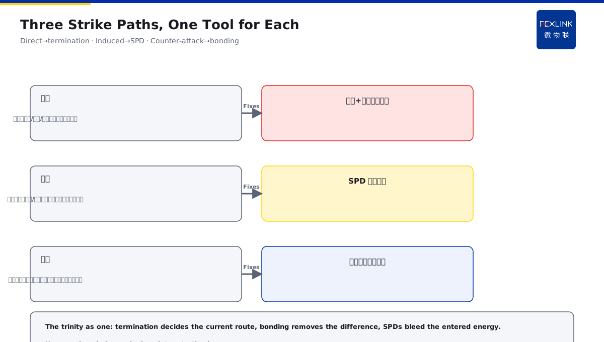
Direct Answer
For outdoor PV arrays, wind-turbine blades and inverters, the lightning risk is high — how should the protection be built as a system? The answer: build the outdoor renewable-energy station as three parts in one whole — the arrays/towers rely on air termination and natural-structure current sharing; all metal supports, cable armoring and cabinets are bonded at their entries; inverters, combiner boxes and grid-connection points get stage-graded SPDs on both the power and signal paths; the dispersed points also need online lightning and SPD-state monitoring under unattended operation.
At a mountain PV plant, inverters failed repeatedly in the storm season; originally only one SPD at the grid-connection point. After the systematic retrofit (array supports and metal frames bonded into the grounding grid, DC and AC sides of the combiner/inverter each with SPDs, dispersed points connected to online lightning and SPD-state monitoring), no further damage occurred. The key distinction: outdoor-station protection is not "installing a few SPDs" but the air-termination—bonding—SPD trinity built as one — termination shares the current, bonding removes the potential difference, SPDs bleed the residual, and online monitoring covers the dispersed points.
Why:
- Termination sharing: the arrays/towers use the natural metal structure to share the direct current;
- Bonding: supports/armor/cabinet entries remove the potential difference;
- Stage-graded SPDs: DC, AC and signal paths bled stage by stage;
- Monitoring backstop: lightning and state visible online for the dispersed unattended points.
Key insight: "Outdoor-station protection = air termination + bonding + SPDs built as one — sharing, removing the difference and bleeding the residual work together, with online monitoring covering the dispersed points."
At a wind farm, after a blade strike the tower-base control cabinet was damaged; the cause was poor bonding and SPD coordination at the cabinet. After re-bonding and adding SPDs to the cabinet power and signal paths, it recovered. Lesson: single-point protection leaves gaps — the three parts must be built as one, and only then the dispersed points are covered.
Overview: thread "termination—bonding—SPD—monitoring" into one defense line. The direct-strike path in an open station is: the strike hits the array/tower first (termination and the natural structure), the current flows along the metal structure to the grounding grid (sharing and bonding), then it tries to enter the cables and equipment from the grid (stage-graded SPDs bleeding). Four things are all necessary: termination decides where the current goes, bonding decides that no dangerous potential difference appears between devices, SPDs decide where the remaining energy is bled, and monitoring decides who knows first when something happens at a dispersed point. The five steps below expand: the direct-strike risk features of open ground and termination, the bonding of array metal supports and cables, the positions of the DC/AC SPDs, lightning and SPD-state monitoring of the dispersed unattended points, and the combination with electrical-safety monitoring.
The three paths of the strike damage: the damage in an outdoor station is not only "the lightning directly hits the device". Path one is direct — the strike hits the modules/blades/towers, the current flows along the structure, and if the sharing path is poor, the local potential rises and may counter-attack the nearby equipment; path two is induction — the lightning current flowing along the down-conductor/cables induces surges into the nearby circuits, entering the devices along the power and signal lines; path three is ground-potential counter-attack — the current entering the ground raises the transient potential on the grounding grid, entering the devices through the grounding connections. Termination handles path one (current takes the structure), bonding handles path three (the difference cannot hit the devices), and SPDs handle path two (bleeding the entered surges). Three paths, three parts, one for each — termination for direct, bonding for counter-attack, SPDs for induction; none can be missing.
1. Direct-Strike Risk Features of Open Ground and Termination
Step one: recognize the risk before building the line.
Risk features:
- Open and unshielded, high direct-strike probability;
- PV arrays/wind turbines are prominent objects;
- Blades/modules vulnerable to direct strikes;
- Many dispersed points, hard to cover with single-point protection.
How termination is done:
- Turbine blades/nacelle designed as natural termination (the blade itself is the path);
- PV array supports/module frames as the termination channel;
- The metal structure shares the direct current;
- Connected into the grounding grid.
The sharing key:
- The current flows along the metal structure;
- Avoid long leads raising the voltage drop;
- Continuous structure, sufficient cross-section;
- A clear sharing path.
Engineering details of termination: the PV array needs no extra lightning rods — the module frames and support structures are natural channels; the key is "structural continuity": supports of one array conduct to each other through connectors, arrays are interconnected with grounding flat steel, all into the grounding grid. The turbine relies on the blade/nacelle design (internal down-conductors, nacelle/tower conduction), with the tower foundation as the natural earth electrode. Three checks on site: first, whether the connections between metal structures are reliable (bolted/welded, low connection resistance); second, whether the termination path cross-section is sufficient (the current channel cannot be a thin wire); third, whether each section of the down path is continuous (a break in the middle = the current changes its route). Termination is not "standing a few rods" but making the whole metal skeleton one continuous discharge channel.
Key insight: "Open stations have a high direct-strike probability — the array/tower uses the natural metal structure for termination and sharing, the current enters the grounding grid through the structure, with short leads and sufficient cross-section."
2. The Bonding of Array Metal Supports and Cables
Step two: pull all metal to the same potential.
The bonding objects:
- Array metal supports/module frames;
- Cable metal armoring/shielding;
- Inverter/combiner cabinets;
- Turbine tower/nacelle.
The bonding practice:
- Supports/frames connected to the grounding grid at multiple points;
- Armoring grounded per the specification (or single-end per it);
- An equipotential busbar at the cabinet entry;
- Removing the potential difference between devices.
Common omissions:
- Adjacent supports not interconnected;
- Armoring left floating, ungrounded;
- Cabinets not connected to the grid;
- The difference destroys the devices.
The bonding check list: the practice must be verified at five places. One, supports: module frames conduct to the supports and the supports connect to the flat steel at multiple points; two, armoring: cable metal armoring grounded per the specification (mind the single-end/two-end rule for shielded signal cables — do not create a ground loop yourself, relating to KD-0193); three, cabinets: inverter/combiner cabinets have an independent equipotential terminal busbar into the grid; four, the tower: nacelle, flanges and the foundation earth form a continuous channel; five, the connection points: check the connection resistance of all bonding points — looseness/corrosion make the bonding fail (relating to the bonding-continuity judgment in KD-0190). Bonding failure is often not "not done" but "done but broken somewhere" — check the connection resistance point by point per the list, clearing the floating points.
Key insight: "Bonding pulls the supports/armor/cabinets to the same potential — multiple connections into the grid, an equipotential busbar at the entry; removing the difference, leaving no floating point."
3. The Positions of the DC/AC SPDs
Step three: where the SPDs go and how they are graded.
The DC-side SPD:
- At the combiner output/inverter DC input;
- Uc selected per the DC system voltage;
- Bleeding the DC-side induced surge;
- Protecting the inverter DC side.
The AC-side SPD:
- At the inverter AC output/grid-connection point;
- Uc selected per the AC system voltage;
- Bleeding the AC-side surge;
- Protecting the grid-connection equipment.
The signal-path SPD:
- Communication/monitoring signal lines;
- Signal SPDs on the signal loops;
- Preventing the signal ports from being destroyed;
- Power + signal dual protection.
The grading principle:
- The power path graded per the boundary;
- DC and AC configured separately;
- The signal path protected alone;
- No path omitted.
The concrete landing points: a typical PV plant needs SPDs at at least five positions. One, the combiner DC output — protecting the combiner and the downstream DC cable; two, the inverter DC input — protecting the DC-side power devices; three, the inverter AC output — protecting the AC side and the grid-connection cable; four, the grid-connection point (box transformer/grid cabinet) — graded T1/T2 per the power-system grading of GB 50057 (relating to the grading thinking of KD-0194); five, the signal path — signal SPDs on the communication/monitoring/data-acquisition ports. On the turbine side: the tower-base control cabinet power gets SPDs, the communication signals get signal SPDs, the nacelle control loop protected as needed. Three parameters together in selection: Uc per the DC system voltage on the DC side, Uc per the AC system voltage on the AC side, Uc per the signal level on the signal side — In/Imax per the boundary capacity, Up per the protected equipment Uw.
Key insight: "SPDs configured per path: DC side at the combiner/inverter input, AC side at the inverter output/grid point, the signal path separately — all three covered, no path omitted."
4. Lightning and SPD-State Monitoring of the Dispersed Unattended Points
Step four: how to know a problem when nobody is there.
The dispersed-point difficulty:
- Points dispersed, unattended;
- The state invisible after a strike;
- Damage found only afterwards;
- Online monitoring is the backstop.
What to monitor:
- The FL lightning-current monitor for strike events/magnitude;
- The FS SPD monitor for the SPD state (leakage/temperature/telemetry);
- The dispersed points connected to one platform;
- Strikes and degradation visible online.
The monitoring value:
- Strike events locatable and reviewable;
- SPD degradation found early (relating to KD-0161);
- Replacement with data (relating to KD-0192);
- Unattended but in control.
The placement and duty logic: unattended does not mean "not watching" — the placement follows the risk. Each combiner/inverter/grid point gets an FS monitor (or the FSS built-in), seeing the leakage/temperature/telemetry; the station entry and high-risk points get FL monitors for strike events and magnitude; key grounding points get FR monitors for the grounding state. The duty logic is three sentences: after a storm, first look at the FL event records to judge which area was struck and which path the current took; then look at the FS data to confirm whether the SPDs in the struck area degraded (whether the leakage/temperature exceeded the limits); finally look at the FR to confirm whether the grounding system degraded from the strike. Monitoring is not "installing more sensors" but placing them per the three links "strike—SPD—grounding", so an event locates to the specific point at once.
Key insight: "Dispersed unattended points rely on online monitoring as the backstop — FL sees the strike events, FS sees the SPD state, all on one platform; strikes reviewable, degradation known early."
5. Combining with Electrical-Safety Monitoring
Step five: lightning protection and electrical safety in one network.
Why combine:
- The station has an electrical-safety monitoring system;
- The lightning data and the electrical data share the source;
- Combining makes the protection more complete;
- Avoiding two systems working separately.
How to combine:
- The FR earth-resistance monitor sees the grounding state;
- The lightning data connected to the electrical-safety platform;
- Strike events linked with device faults for attribution;
- One picture of the whole station.
The combined value:
- Grounding degradation found early;
- Strikes and device faults analyzable together;
- The protection effect verifiable;
- O&M decisions with data.
Key insight: "Combining lightning protection with electrical-safety monitoring — FR sees the grounding, FL sees the strikes, FS sees the SPDs; one platform, the protection effect verifiable."
6. Product Implementation: The Trinity Plus Monitoring as One
WeiWuLian products manage outdoor-station lightning protection:
- FL Lightning-Current Monitor: strike events/magnitude online;
- FS SPD Monitor: SPD state/leakage/telemetry online;
- FR Earth-Resistance Monitor: grounding state/resistance online;
- One platform: termination—bonding—SPD—monitoring in one picture.
The design principle in one sentence: "Termination sharing + bonding + stage-graded SPDs built as one, with FL/FS/FR online monitoring as the backstop — dispersed points reviewable after strikes, degradation known early."
7. Common Configuration Misjudgments
- "Only SPDs are enough": ignoring termination and bonding. Result: a messy current path and the difference hitting the devices. Correct: the trinity as one.
- "Supports need no grounding": ignoring the bonding. Result: the difference destroys the devices. Correct: bond the supports/armor/cabinets.
- "Only the AC side": ignoring the DC side and the signals. Result: DC/signal ports destroyed. Correct: cover all three paths.
- "No monitoring for unattended points": ignoring the visibility. Result: damage found only afterwards. Correct: online monitoring as the backstop.
- "Separating lightning and electrical safety": ignoring the combination. Result: data islands. Correct: one platform.
Scope and Limitations
This article gives the integrated lightning-protection scheme for outdoor PV/wind stations (termination, bonding, stage-graded SPDs, dispersed-point monitoring, combination with electrical safety), applicable to the design and optimization of renewable-energy station lightning protection. The exact parameters and requirements follow GB 50057-2010, GB/T 18802.11 and the manufacturers' data; this article explains only the integrated building logic and points. All cases are anonymized (a mountain PV plant, a wind farm) and do not refer to any specific customer.