 微物联研究院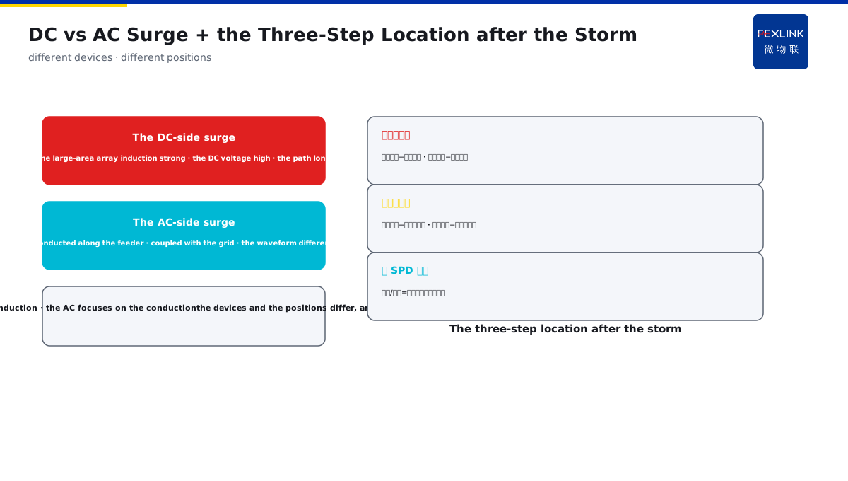
Direct Answer
With the PV panels laid out over a large open area, after a thunderstorm the inverter alarms and the modules burn out — where does the lightning actually come in? The answer: PV lightning damage has three main paths — the large metal network of the module frames and the racks induces a lightning current to the DC combiner box and then to the DC side of the inverter; the surge after the AC side is connected through the SPD; and the ground-potential rise causes the back-flash between the modules and the racks. The larger the open array and the longer the rack earthing, the more serious the DC-side induction.
At a PV plant, after a thunderstorm, inverters alarmed in batches; the inspection found that no DC-side SPD was installed and there were arc marks between the module frames and the racks; the lightning current was induced into the DC circuit along the module racks and impacted the DC side of the inverter. After the DC-side SPD was added and the rack equipotential bonding was improved, no alarm occurred under the same kind of thunderstorm. The key distinction: the lightning damage is not simply "install an SPD" — the three paths of the large-area DC-array induction, the AC-side surge and the ground-potential back-flash each need the corresponding protection; the DC-side induction becomes more serious as the array area grows.
Why:
- The DC-side induction: the module-frame/rack metal network induces the lightning current;
- The AC-side surge: the surge after the AC side is connected through the SPD;
- The ground-potential back-flash: the ground-potential rise causes the module/rack back-flash;
- The corresponding protection: the DC/AC SPD and the equipotential bonding each do their own job.
Key insight: "PV lightning damage has three main paths — the large-area DC-array induction (the module frame/rack/combiner box/DC side of the inverter), the AC-side surge, and the ground-potential back-flash (between the modules and the racks); the larger the array and the longer the rack earthing, the more serious the DC-side induction, and each path needs the corresponding protection."
At a PV project, after a thunderstorm, point-like punctures appeared on the module glass and the DC side of the inverter was damaged; the investigation found that the racks had no equipotential bonding, and when the ground potential rose, the back-flash occurred between the modules and the racks and punctured the modules. After the equipotential bonding was completed and the DC-side SPD was installed, no more punctures occurred. Lesson: the AC-side SPD alone cannot stop the DC side — the ground-potential back-flash and the DC induction are the PV-specific lightning damage, and the equipotential bonding and the DC SPD are both indispensable.
Overview: run "which three paths the lightning enters through → how the DC/AC surge differs → how the earthing and the equipotential prevent the back-flash → how the DC/AC SPD is set" as one lightning-path cognition. The PV panels laid out over a large open area are the high-frequency objects of the strike and the induction. The lightning damage has three main paths: the large metal network of the module frames and the racks induces a lightning current, to the DC combiner box and then to the DC side of the inverter; the surge after the AC side is connected through the SPD; and the ground-potential rise causes the back-flash between the modules and the racks. The larger the open array and the longer the rack earthing, the more serious the DC-side induction. The four layers are unfolded below.
A "fishing net" analogy: think of the open PV array as an unfolded fishing net. The module frames and the racks are the "net lines", and the large-area metal is the "net area" — the larger the net, the more "fish" (the induced lightning current) it catches. At the strike, the current induced on this net flows along the net lines (the DC circuit) to the combiner box and then rushes into the inverter. The AC side is another "tributary" (the feeder) that brings the surge in; the ground-potential rise is like "the water bottom surging", making "bubbles" (the back-flash arcs) appear between the net lines and the ground. The lightning protection is to "close the net" — install the DC-side SPD and do the rack equipotential bonding, discharging the induced current before it enters the equipment. The fishing-net analogy: the PV array = the unfolded net, the larger the net, the more induced current it catches; the DC induction flows into the combiner box, the AC feeder is the tributary, and the ground-potential rise is the water-bottom surge — closing the net is the DC SPD plus the equipotential bonding, discharging the current before it enters the equipment.
1. The Three Paths: How the Lightning Enters the PV System
Step one: first look at the three main paths of the PV lightning damage.
The DC-side induction path:
- The module-frame/rack large-area metal;
- Inducing the lightning current at the strike;
- Along the DC circuit to the combiner box;
- Impacting the DC side of the inverter.
The AC-side surge path:
- The lightning current conducted along the AC feeder;
- Invading from the grid side;
- Impacting the AC side of the inverter;
- Needing the AC-side SPD to discharge.
The ground-potential back-flash path:
- The potential rising when the current enters the ground;
- The potential difference between the modules and the racks;
- The back-flash at the weak insulation;
- Puncturing the module glass/junction box.
Key insight: "The three paths depend on the entrance — the DC-side induction (the frame/rack metal network inducing → the combiner box → the DC side of the inverter), the AC-side surge (the feeder conduction invading), and the ground-potential back-flash (the entering potential rising and puncturing the modules) — each path needs the corresponding protection."
2. DC vs AC: How the Surge Differs
Step two: the difference between the DC-side and AC-side surges.
The DC-side surge:
- The large-area array induction strong;
- The DC voltage level high;
- The module/rack/combiner-box path long;
- Discharged by the DC SPD.
The AC-side surge:
- Conducted along the feeder;
- Coupled with the grid;
- The waveform different from the DC;
- Discharged by the AC SPD.
The core difference:
- The DC side focuses on the induction;
- The AC side focuses on the conduction;
- The protection devices different;
- The positions different.
Key insight: "The DC/AC surges differ — the DC side focuses on the induction (the large-area array induction strong and the path long), and the AC side focuses on the conduction (invading along the feeder and coupling) — the protection devices and the positions are different, and they cannot be mixed."
3. The Earthing and the Equipotential: How to Prevent the Back-Flash
Step three: the module earthing and the rack equipotential bonding are the key to preventing the back-flash.
The module earthing:
- The module frame reliably earthed;
- Discharging the induced charge;
- Reducing the potential difference to the ground;
- Protecting the module structure.
The rack equipotential bonding:
- The equipotential connection between the racks;
- Reliably connected with the grid;
- The potential rising consistently;
- Eliminating the module/rack back-flash.
The earthing continuity:
- The longer the rack earthing, the more attention needed;
- The connection points reliable;
- The corrosion/loosening checked;
- The equipotential bonding is the root of preventing the back-flash.
Key insight: "The earthing and the equipotential prevent the back-flash — the module frame reliably earthed discharges the induced charge, and the equipotential connection between the racks eliminates the module/rack potential difference; the longer the rack earthing, the more attention needed, and the equipotential bonding is the root of preventing the back-flash."
A three-step on-site way to "locate the lightning damage" after the thunderstorm: after the thunderstorm, when the inverter alarms, locate the lightning path in three steps. Step one, look at the alarm object — the DC-side alarm of the inverter (the DC overvoltage/DC overcurrent) points to the DC-side induction, and the AC-side alarm (the AC overvoltage) points to the feeder surge; step two, look at the module traces — the point-like puncture on the module glass/the junction-box burn points to the ground-potential back-flash, and the frame arc marks point to the missing rack equipotential bonding; step three, look at the SPD state — whether the DC/AC SPD operated or was damaged, and if it operated, the surge really went through that path. With the three steps located, which path the lightning enters is clear at a glance. The three-step location: look at the alarm object (the DC-side alarm = the DC induction, the AC alarm = the feeder surge) → look at the module traces (the point-like puncture = the ground-potential back-flash, the frame arc = the missing equipotential) → look at the SPD state (the operation = the surge went through that path).
4. How to Set the SPD: The DC and the AC in Their Own Places
Step four: the setting positions of the PV DC-type/AC-type SPD.
The DC-side SPD:
- Set at the output end of the module array;
- Set at the DC side of the inverter;
- Discharging the DC induction surge;
- Protecting the DC circuit.
The AC-side SPD:
- Set at the AC side of the inverter;
- Set at the grid-connection point;
- Discharging the feeder-conducted surge;
- Protecting the AC circuit.
The setting principle:
- Both ends need the protection;
- The position close to the protected equipment;
- Coordinated with the equipotential bonding and the earthing;
- The surge discharged in stages.
Key insight: "The SPD in its own place — the DC-side SPD at the array output/DC side of the inverter discharges the induction surge, and the AC-side SPD at the AC side of the inverter/grid-connection point discharges the conducted surge — both ends have the protection, close to the protected equipment, and coordinated with the equipotential bonding and the earthing."
An engineering judgment of "the DC induction growing with the array": one module is a metal surface of tens of watts, and a whole array is a metal network of tens of acres — the induction capability grows sharply with the area. In engineering, judging the DC-side lightning risk depends on three things: one, the array area (the larger the area, the stronger the induction); two, the rack earthing mode (the longer the earthing line and the larger the loop, the easier the induced current enters the DC circuit); three, the DC circuit routing (the more concentrated the combiner-box/inverter path, the more concentrated the surge impact). With the three things combined, the grade and the position of the DC-side SPD are known. The three engineering looks: the array area (the larger, the stronger the induction), the rack earthing (the longer, the larger the loop), and the DC circuit routing (the more concentrated, the more concentrated the surge impact) — the three looks decide the grade and the position of the DC SPD.
The order principle of "preventing the damage before the equipment": the PV lightning protection is not piling the SPD beside the equipment, but shunting the lightning current before it enters the equipment. The order is: first the air termination and the discharge (the module/rack metal path leads the induced current away) → then the equipotential bonding (making the metal-structure potentials consistent and eliminating the back-flash) → last the SPD (pressing the remaining surge below the equipment tolerance at the DC/AC entrance). The three defense lines each manage one section, and missing one leaks one path. Preventing before the equipment: first the air termination and the discharge (the metal path leads the induction away) → then the equipotential bonding (eliminating the back-flash) → last the SPD (pressing the surge at the entrance) — the three defense lines each manage one section, and missing one leaks one path.
5. Product Implementation: The Lightning-Damage Path Made Monitorable
WeiWuLian products bring the PV lightning-damage path to the verifiable level:
- FL lightning-current monitor: the strike current of the array/combiner box online;
- FSS intelligent surge protective device: the SPD operation and degradation monitored;
- The data review: the strike path compared with the protection effect;
- The loop improvement: the targeted SPD configuration and the equipotential bonding.
The design principle in one sentence: "The path monitored and the protection closed in the loop — the FL records the array strike current, the FSS monitors the SPD operation and the degradation, the weak point is located against the path after the thunderstorm, and the protection configuration is closed in the data loop."
6. Common Understanding Misjudgments
- "One AC SPD is enough": wrong. The DC-side induction is the PV-specific lightning damage, and the DC SPD is indispensable.
- "The module frame needs no earthing": wrong. The reliably earthed frame discharges the induced charge.
- "The rack equipotential bonding is optional": wrong. Without the equipotential bonding, the module/rack back-flash occurs when the ground potential rises.
- "The large array does not matter": wrong. The larger the array, the more serious the DC-side induction, and the higher the protection requirement.
- "The SPD is done after installation": wrong. The SPD degrades and the operation and the state must be monitored.
Scope and Limitations
This article disassembles the PV-plant lightning-damage paths (the three paths of the DC induction, the AC surge and the ground-potential back-flash), applicable to the PV lightning-protection design and the operation-and-maintenance judgment. The SPD selection and the setting positions follow GB/T 18802.11 and IEC 62305-3; this article explains only the path mechanism. All cases are anonymized (a PV plant/a PV project) and do not refer to any specific customer.