 微物联研究院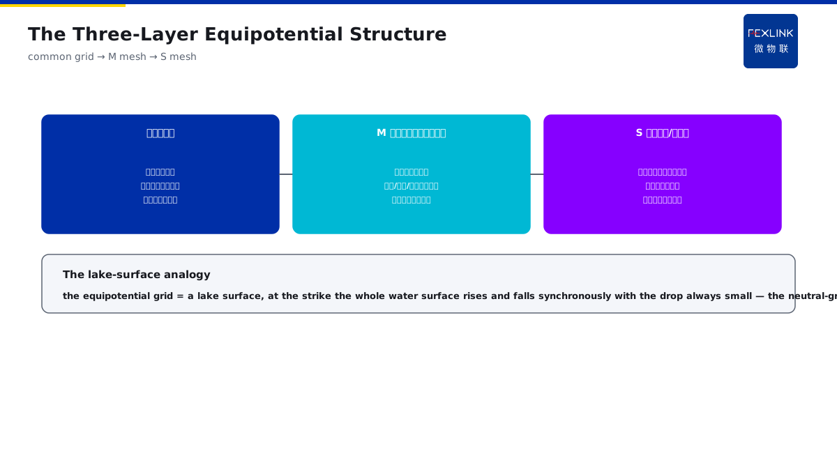
Direct Answer
The data center requires the cabinets, cable trays, UPS and the floor reinforcement to be equipotentially bonded into one network — how does this network actually work? The answer: the data center takes the building common grounding grid as the base, lays the equipotential bonding grid (the M mesh) in the machine room and bonds it to the cabinets, cable trays and the anti-static floor reinforcement at multiple points, forming an approximately equipotential "zero-reference plane"; the S mesh (the signal/local) then makes the strengthened bonding around the sensitive equipment, so that at the strike or the surge all the equipment reference points rise synchronously and the potential difference between the equipment is eliminated.
At a data center, during the thunderstorm season, the network equipment frequently mis-operated; the investigation found that the cabinets and the cable trays were not included in the equipotential grid, and at the strike the reference potentials of the equipment differed and a potential difference appeared between the signal lines. After the cabinets, cable trays and the anti-static floor reinforcement were all included in the M mesh with the multi-point bonding, no mis-operation occurred under the same kind of thunderstorm. The key distinction: the equipotential network is not "one more ground wire" — the M mesh bonds the cabinets/trays/floor reinforcement into one grid, forming the zero-reference plane; at the strike or the surge all the reference points rise synchronously and there is no potential difference between the equipment; the S mesh then makes the strengthened bonding around the sensitive equipment.
Why:
- The common grounding grid: the building foundation grid as the lowest layer;
- The M mesh: the equipotential bonding grid in the machine room;
- The S mesh: the strengthened bonding around the sensitive equipment;
- The synchronous rise: all the reference potentials consistent.
Key insight: "The equipotential grid is layered in three — the common grounding grid forms the base, the M mesh bonds into a grid in the machine room (the cabinets/trays/floor reinforcement at multiple points), and the S mesh strengthens the bonding around the sensitive equipment — at the strike or the surge all the reference points rise synchronously and there is no potential difference between the equipment."
At a data center, the equipment in the UPS supply area frequently alarmed; the investigation found that the anti-static floor reinforcement was not included in the equipotential network, and at the strike the reference potential in that area was abnormal. After the floor reinforcement was connected to the M mesh, the alarms disappeared. Lesson: the equipotential network "fails when one bonding point is missing" — the "invisible metal" such as the floor reinforcement and the cable trays must all be included in the grid for the zero reference to be complete.
Overview: run "how the common grounding grid → the M mesh → the S mesh are layered → how the grid makes the reference points rise synchronously → where the neutral-ground voltage sits in the system → where the construction points are" as one equipotential cognition. The data center requires the cabinets, cable trays, UPS and the floor reinforcement to be equipotentially bonded into one network. This network takes the building common grounding grid as the base, lays the equipotential bonding grid (the M mesh) in the machine room and bonds it to the cabinets, cable trays and the anti-static floor reinforcement at multiple points, forming an approximately equipotential zero-reference plane; the S mesh then makes the strengthened bonding around the sensitive equipment, so that at the strike or the surge all the equipment reference points rise synchronously and the potential difference between the equipment is eliminated. The four layers are unfolded below.
A "lake surface" analogy: think of the equipotential grid as a lake surface. A lake surface is naturally flat — no matter which point is disturbed (the strike/surge), the whole water surface rises and falls together, and the "drop" (the potential difference) between the points always stays small. The M mesh is this lake: the cabinets, cable trays and the floor reinforcement are all "connected" into the same water surface, and at the strike the whole water surface rises and falls synchronously, with the drop (the potential difference) between the equipment pressed to the minimum. The S mesh is like deepening the connection at the "lake center" of the sensitive equipment, making the drop between the signal reference points smaller. The neutral-ground voltage is "the ruler of the lake-surface flatness" — when the drop exceeds the limit, it shows where the lake surface is uneven. The lake-surface analogy: the equipotential grid = a lake surface, at the strike the whole water surface rises and falls synchronously with the drop between the points always small; the S mesh = the deepened connection at the lake center; the neutral-ground voltage = the ruler of the lake-surface flatness.
1. The Three-Layer Structure: Common Grounding Grid → M Mesh → S Mesh
Step one: first look at the three-layer structure of the equipotential system.
The common grounding grid:
- The building foundation grid;
- The meeting point of all the earthing;
- The lightning current dispersing into the soil;
- The lowest-layer reference.
The M mesh (the equipotential bonding grid):
- The grid laid in the machine room;
- The cabinets/trays/floor reinforcement bonded;
- Forming the zero-reference plane;
- The equipment reference points consistent.
The S mesh (the signal/local):
- The strengthened bonding around the sensitive equipment;
- The signal reference points reinforced;
- Eliminating the potential difference between the signals;
- Working together with the M mesh.
Key insight: "The three layers depend on the level — the common grounding grid forms the base (all the earthing meets), the M mesh bonds into a grid in the machine room (the cabinets/trays/floor reinforcement), and the S mesh strengthens around the sensitive equipment — the three layers together form the zero reference."
2. How the Grid Works: The Reference Points Rise Synchronously
Step two: how the equipotential grid makes all the reference points "rise synchronously".
The multi-point bonding:
- The cabinets/trays/floor reinforcement bonded at multiple points;
- The grid impedance low;
- The potential difference flattened;
- Forming the zero-reference plane.
The synchronous rise:
- At the strike or the surge;
- The grid potential rising wholly;
- All the equipment reference points consistent;
- No potential difference between the equipment.
Why safe:
- The dangerous thing is the potential difference;
- Not the absolute value of the potential;
- The synchronous rise without difference is safe;
- The nature of the grid is the voltage equalization.
Key insight: "The grid works through the synchronous rise — the multi-point bonding lowers the grid impedance, the grid rises wholly at the strike or the surge, and all the reference points are consistent — the dangerous thing is the potential difference rather than the absolute value, and the synchronous rise without difference is safe."
3. The Neutral-Ground Voltage: Its Position in the Equipotential System
Step three: the position of the neutral-ground voltage over the limit in the equipotential system.
The sources of the neutral-ground voltage:
- The potential difference between the neutral and the ground;
- From the three-phase unbalance/harmonics;
- From the grounding-path impedance;
- From the incomplete equipotential bonding.
The over-limit influence:
- The equipment mis-operation;
- The signal quality degraded;
- The data error/packet loss;
- The sensitive equipment damaged.
The role of the equipotential bonding:
- The complete equipotential bonding lowers the neutral-ground difference;
- The monitoring finds the weak point;
- The difference falls after the grid repair;
- The neutral-ground voltage is the health indicator of the equipotential bonding.
Key insight: "The neutral-ground voltage is the health indicator of the equipotential bonding — from the three-phase unbalance/harmonics/the grounding-path impedance/the incomplete equipotential bonding, the over-limit causes the equipment mis-operation; the complete equipotential bonding lowers the difference, and the monitoring finds the weak point."
A three-step way to "check the neutral-ground voltage" on site: when the machine-room neutral-ground voltage exceeds the limit, locate it in three steps. Step one, look at the measurement points — measure the neutral-ground voltage at the cabinet power entrance and compare the multi-point measurements; step two, look at the pattern — the voltage fluctuating with the load points to the three-phase unbalance/harmonics, the voltage appearing with the strike/surge points to the incomplete equipotential bonding, and the constantly high voltage points to the grounding-path impedance; step three, look at the equipotential bonding — whether the cabinet/tray/floor-reinforcement connections are complete and whether the connection points are corroded or loose. After the three steps, the cause of the over-limit neutral-ground voltage lands on the grounding, the equipotential bonding or the load. The three-step neutral-ground check: look at the measurement points (the multi-point comparison at the cabinet entrance) → look at the pattern (fluctuating with the load = unbalance/harmonics, appearing with the strike = the incomplete equipotential, constantly high = the grounding impedance) → look at the equipotential bonding (the complete connections/the corroded points).
4. The Construction Points: The Cabinets, the Trays, the Bonding
Step four: the construction points of the cabinets, the cable trays and the tray bonding.
The cabinet bonding:
- The cabinet earthing terminal bonded;
- Reliably connected with the grid;
- The contact surface treated;
- The connection points anti-corrosion.
The tray bonding:
- The tray segments bonded across;
- The bonding wire reliable;
- The connection-point resistance small;
- The continuous conductor through.
The floor reinforcement:
- The anti-static floor reinforcement bonded;
- Included in the equipotential grid;
- The hidden metal also connected;
- The multi-point bonding complete.
Key insight: "The construction points depend on the bonding — the cabinet earthing terminal enters the grid, the tray segments bond reliably across, and the anti-static floor reinforcement is included in the grid — the hidden metal also connected, the multi-point bonding complete, and the zero reference established."
The acceptance check of the "grid completeness": after the equipotential grid is done, check the completeness in four points. One, the cabinets — whether every cabinet earthing terminal enters the grid and the contact surface is treated by the spot check; two, the trays — whether all the segment bonding is done and the bonding-wire resistance is qualified; three, the hidden metal — whether the anti-static floor reinforcement, the water pipes and the air ducts are included in the grid; four, the S mesh — whether the sensitive-equipment signal reference points have the strengthened bonding. After the four-point check, whether the grid "has a leak" is clear at a glance. The four-point acceptance: the cabinet terminals all enter the grid, the tray bonding all done, the hidden metal (the floor reinforcement/water pipes/air ducts) all included, and the S-mesh strengthened bonding for the sensitive equipment — the four-point check shows the grid has no leak.
5. Product Implementation: The Zero Reference Made Verifiable
WeiWuLian products bring the equipotential system to the verifiable level:
- ESP neutral-ground voltage monitor: the neutral-ground voltage monitored online;
- The trend warning: the equipotential degradation found in advance;
- The data review: the reference points compared after the strike;
- The loop improvement: the grid-repair effect verified.
The design principle in one sentence: "The equipotential monitored and the hidden danger found early — the ESP monitors the neutral-ground voltage online, the abnormal trend hints the equipotential weak point, the reference points are rechecked after the strike, and the grid-repair effect is closed in the data loop."
6. Common Understanding Misjudgments
- "One more ground wire is the equipotential bonding": wrong. The equipotential bonding is the grid multi-point bonding, not one more ground wire.
- "Only the cabinet earthing matters": wrong. The hidden metal such as the trays and the floor reinforcement must all enter the grid.
- "The neutral-ground voltage does not matter": wrong. The over-limit causes the equipment mis-operation and is the health indicator of the equipotential bonding.
- "The S mesh is optional": wrong. The sensitive-equipment signal reference points depend on the S-mesh strengthening.
- "The equipotential bonding is done after installation": wrong. The connection points corrode/loosen and degrade, and must be monitored and verified.
Scope and Limitations
This article explains the mechanism of the data-center equipotential grid M/S mesh (the three-layer structure, the synchronous rise, the neutral-ground-voltage position, and the construction points), applicable to the machine-room equipotential design and the operation-and-maintenance judgment. The specific bonding and construction requirements follow GB 50343-2012 and GB 50174; this article explains only the mechanism. All cases are anonymized (a data center/a machine room) and do not refer to any specific customer.