 微物联研究院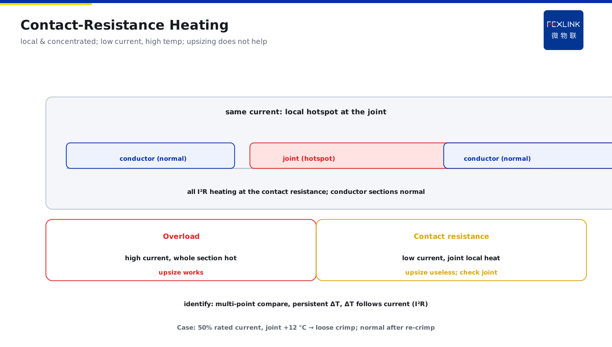
Direct Answer
The temperature near a cable intermediate joint is high, but the circuit current is not large — where is the problem? The answer: it points to increased contact resistance — loose crimping, oxidation, or poor workmanship at the joint makes the local resistance greater than the adjacent section; at the same current, heating concentrates at the joint rather than the conductor. This is the typical "temperature rise with flat current" signal; arrange an outage inspection of the joint, not a larger cable.
A distribution circuit ran at only half its rated current, yet temperature monitoring showed the cable intermediate joint 12 °C hotter than other sections. Judging by "temperature rise with flat current": current is not high but the joint is hot, meaning high contact resistance at the joint and heating concentrated there. Outage inspection found loose crimping (insufficient crimping torque, loosened by vibration). After re-crimping, temperature returned to normal. Following the intuition "upgrade the cable" would have been completely wrong. A hot joint with low current — the first suspect is contact resistance, not overload.
Because:
- "Temperature rise with flat current" is the typical contact-problem signal: overload means high current + high temperature; low current with high temperature means the heat comes from local resistance;
- Heating concentrates at the joint, not the conductor: contact resistance far exceeds the adjacent conductor section, so I²R heating is all at the joint;
- Loose crimping, oxidation, and poor workmanship are the three main causes: insufficient torque, oxidized contact surface, non-standard crimping process;
- Oxidation worsens in a positive feedback loop: high contact resistance → heating → faster oxidation → higher resistance → hotter — it degrades progressively if left untreated.
Key insight: "low-current high temperature" at a cable joint points to contact resistance; the disposition is an outage inspection of the joint. A larger cable does not solve contact resistance — check the joint first.
At one plant, a cable joint temperature was abnormal: current normal but the joint ran 8 °C hotter than other sections; IR confirmed a local hotspot at the joint. Outage inspection found severe oxidation (long-term humid environment). After treatment (cleaning, re-crimping, antioxidant coating), temperature returned to normal. Oxidation is a common cause of increased joint contact resistance — humid environments need regular inspection.
1. Heating Characteristics of Increased Contact Resistance
First recognize contact-resistance heating:
Heating characteristics:
- Heating concentrated locally at the joint (at the contact resistance);
- At the same current, temperature rise higher than adjacent sections (clear ΔT under identical current);
- Temperature rise grows with current (I²R), but the "current–rise" curve is steeper than a normal section;
- IR shows a local hotspot (clear joint-vs-conductor temperature difference).
Difference from overload:
- Overload: overall heating (the whole cable is hot), high current;
- Contact: local heating (only the joint is hot), current not high;
- Overload responds to a larger section; contact does not.
How to identify:
- Compare multiple temperature points on the same circuit (joint vs adjacent-section ΔT);
- ΔT persists (not transient) → contact problem;
- ΔT changes with current (current up, ΔT up) → I²R characteristic confirmed.
Key insight: contact-resistance heating is "local and concentrated." The joint hotter than adjacent sections, current not high, ΔT following current — clear characteristics, clear direction.
2. Joint-vs-Adjacent-Section Temperature Comparison
Quantify with the ΔT comparison:
ΔT comparison method:
- Measure several sections of the same circuit (joint, 1 m before/after the joint, mid-span);
- Compute joint-vs-adjacent ΔT;
- Normal joint: small ΔT (basically the same at the same current);
- Abnormal joint: obvious ΔT (ΔT ≥ 5–8 °C, persistent).
How to judge:
- Small ΔT (<3 °C) → joint normal;
- Obvious ΔT (≥5 °C) → suspect increased contact resistance;
- Large ΔT that grows with current → contact problem confirmed;
- Combine with IR review (hotspot position = contact point).
Notes:
- Compare at the same class of current (ΔT at different currents is not comparable);
- Record the "current–ΔT" correspondence (multiple data sets);
- The platform auto-computes the joint-vs-adjacent ΔT trend.
How to do the IR review:
- Scan the whole cable with an IR camera (find the hotspot distribution);
- Normal sections uniform, an obvious hotspot at the joint = contact problem;
- Hotspot extent reflects the degraded contact area (expanding hotspot = worsening);
- IR and online temperature corroborate each other (consistent ΔT is credible);
- Review at stable load (same-current comparison is most accurate).
Key insight: the ΔT comparison is the quantitative basis. ΔT ≥ 5 °C between joint and adjacent section at the same current — contact-resistance suspicion stands; arrange an outage inspection.
3. Manifestations of Poor Crimping Workmanship
Crimping-process problems are a common cause of hot joints:
Poor-crimping manifestations:
- Insufficient crimping torque (loose joint, looser after vibration);
- Wrong crimping die (incomplete crimp);
- Too short a crimp length (small contact area);
- Copper–aluminum mixed connection without a transition joint (electrochemical corrosion).
How to find it:
- Outage inspection of the joint: torque review (loose?);
- Visual inspection: are the crimp marks standard (number/position of crimps)?
- Temperature: a poorly crimped joint has a local hotspot;
- IR/temperature review to locate.
Disposition:
- Re-crimp (torque per procedure, qualified tooling);
- Copper–aluminum transition joint (for mixed connections);
- Re-measure after crimping (torque review + temperature confirmation).
Key insight: crimping workmanship is a source problem. Insufficient torque, incomplete crimps, mixed-connection corrosion — inspect the joint appearance and torque; solve at the source.
4. Oxidation's Positive Feedback
Oxidation progressively worsens the contact problem:
Oxidation positive-feedback mechanism:
- High contact resistance → joint heating;
- Heating → faster oxidation (heat + humidity);
- Oxidation → higher contact resistance;
- Higher resistance → hotter — a vicious cycle.
Environments prone to oxidation:
- Humid environments (cable trenches, tunnels, outdoors);
- Corrosive environments (chemical plants, coasts);
- Copper–aluminum mixed connections (accelerated electrochemical corrosion).
How to find it:
- Joint appearance discoloration (oxide layer);
- IR hotspot steadily expanding (oxide area growing);
- ΔT trend growing (period-over-period worsening).
Disposition:
- Clean the oxidized surface (grind off the oxide layer);
- Apply antioxidant/conductive grease;
- Seal against moisture (moisture-proofing);
- Regular inspection (shorter intervals in humid environments).
Oxidation check list:
- Appearance: joint/termination discolored (green/black) → oxidation;
- Environment: water in cable trenches, humid tunnels, outdoor sun/rain;
- Trend: IR hotspot expanding period-over-period, ΔT steadily growing;
- Re-measure: ΔT before/after treatment (effective = ΔT drops).
Key insight: oxidation worsens in positive feedback. Untreated, it gets hotter and hotter — clean, antioxidant, moisture-proof; break the cycle.
5. Disposition and Re-Measurement Arrangement
Once the contact problem is confirmed, dispose per procedure:
Disposition steps:
- Outage (work permit per procedure);
- Inspect the joint (appearance, torque, oxidation);
- Clean/grind the contact surface (remove oxide);
- Re-crimp (torque per procedure) or replace the joint;
- Apply antioxidant / seal against moisture;
- Energize and re-measure (confirm ΔT gone).
Re-measurement arrangement:
- Immediately after energizing (confirm hotspot gone);
- 24 h later (confirm stability);
- One week later (confirm no recurrence);
- Include in scheduled temperature monitoring (denser in humid environments).
Prevention:
- Joint temperature into online monitoring (EST Multi-Channel Temperature Controller);
- Auto-alert on the ΔT trend (joint vs adjacent section);
- Regular joint inspection in humid environments.
Key insight: disposition is "outage inspection → clean and re-crimp → re-measure to confirm." The job is done only when ΔT is gone — re-measure three times to prevent recurrence.
6. Product Landing: Cable-Joint Diagnosis
FEXLINK products bring cable-joint diagnosis to the field:
- EST Multi-Channel Temperature Controller: multi-point temperature at the joint and adjacent sections (auto ΔT comparison);
- FEXLINK-BMS Busbar Monitoring System: busbar/joint temperature + current monitoring (current–ΔT on the same axis);
- ESX Edge Computing Gateway: joint-vs-adjacent ΔT trend analysis; auto-alert at ΔT ≥ 5 °C;
- The platform outputs "suspected increased contact resistance" with disposition advice (outage inspection of the joint);
- ΔT trend visualization; oxidation-worsening auto-warning (prevents positive-feedback degradation).
Design principle in one sentence: turn "I can't understand why it is hot" into "ΔT comparison locks onto contact." Current–ΔT linkage automatically locates the joint problem — disposition without detours.
7. Common On-Site Mistakes
- Ruling out heating because current is not high: concluding "low current cannot be hot." Consequence: contact-resistance heating is missed. Correct: low current with high temperature is exactly the contact-problem signal.
- Directly upgrading the cable: assuming the section is insufficient. Consequence: contact problem unsolved, money wasted. Correct: check the joint's contact resistance first.
- Not measuring the adjacent section: looking only at the joint's absolute temperature. Consequence: no comparison, no basis. Correct: compare joint vs adjacent section ΔT.
- Ignoring oxidation worsening: joint inspection without cleaning/moisture-proofing. Consequence: positive-feedback worsening, hotter and hotter. Correct: clean + antioxidant + moisture-proofing.
- No re-measurement after treatment: leaving after re-crimping. Consequence: crimp recurrence unknown. Correct: three re-measurements after energizing (immediate/24 h/one week).
Scope and Limitations
This article discusses diagnosing "low-current high temperature" at cable intermediate joints (increased contact resistance, ΔT comparison, crimping workmanship, oxidation positive feedback) for power-cable joints/terminations in service. The judgment indicators (e.g., 5–8 °C ΔT) are engineering experience references; actual practice follows cable section, joint type, and operating environment. Joint inspection and re-crimping involve outage work and must follow procedures by qualified personnel. Oxidation treatment (grinding, antioxidant coating) must follow process requirements. Online monitoring data is managed uniformly through the platform to form trend alerts. All cases are anonymized (a certain circuit / plant) and do not refer to any specific customer.