 微物联研究院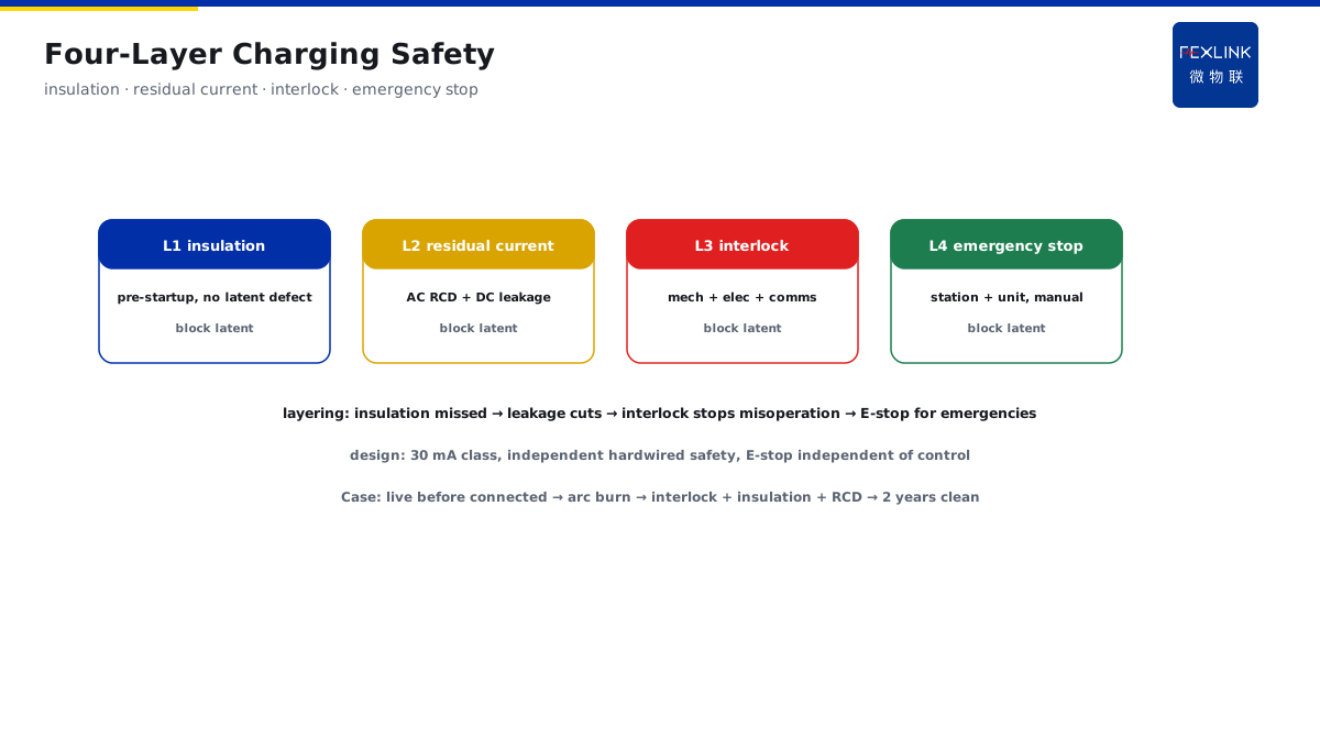
Direct Answer
For charging-station design, what exactly does the standard require for insulation monitoring and protection? The answer: GB/T 18487.1 specifies safety requirements for conductive charging systems — including insulation-resistance monitoring, touch-current protection, emergency stop, and interlocking; landing design requires insulation detection before every startup, residual-current protection, and reliable interlocking. Understanding these requirements is the compliance baseline for charging-station electrical-safety design.
A new charging station (30 DC chargers) was designed per GB/T 18487.1: each charger performs insulation-resistance detection before every startup (closes only when the detection passes); the feeder is configured with residual-current protection (RCD); charging connectors have mechanical + electrical interlocking (no energization unless properly connected); the station has emergency-stop buttons (can cut all outputs). Acceptance passed on the first attempt, with no rectification items from the utility inspection. The core of landing GB/T 18487.1 is "insulation + protection + interlocking": pre-startup insulation detection, residual-current protection, reliable interlocking and emergency stop — the compliance baseline for charging safety design, accepted in one pass.
Because:
- Charging is a three-way human-vehicle-charger interaction: safety requirements are stricter than ordinary distribution (frequent human contact);
- Insulation is the first line of defense: pre-startup detection prevents energizing with a latent defect;
- Residual-current protection is the human-safety bottom line: touch/leakage current is cut immediately;
- Interlocking prevents misoperation: no energization unless connected properly, preventing arc injury and damage.
Key insight: GB/T 18487.1 is the compliance baseline for charging safety. Insulation + protection + interlocking — with all three elements in place, the design passes.
At one plant's charging station, a charging gun became live before being fully connected, and an operator was arc-burned on contact. Rectified per the standard: added connection-confirmation interlocking (no power unless locked), pre-startup insulation detection, and feeder residual-current protection. Two years of operation with no incidents — behind the standard's clauses are accident lessons: insulation, protection, and interlocking are each critical to preventing personal injury.
1. Pre-Startup Insulation-Resistance Monitoring
Step one: how to manage insulation.
Standard requirements:
- Insulation-resistance detection before every charging startup;
- Detection object: DC positive/negative poles to ground;
- Charging is allowed only when the detection passes;
- Detection failure: report insulation fault, prohibit charging.
Detection points:
- Timing: before every startup (not once at installation);
- Method: injection/bridge method (built into the charger);
- Judgment: insulation resistance below the threshold fails (per voltage level);
- Re-test: restore charging only after the fault is handled and the re-test passes.
Design landing:
- Built-in insulation-detection module in the charger (pre-startup self-check);
- Output interlocked/blocked on insulation fault (no power);
- Insulation data recording (trend analysis: slow decline = moisture/aging);
- Alarm linkage (insulation anomaly notifies operations).
Common problems:
- Tested once (at installation acceptance) and never re-tested — does not meet "before every startup";
- Insulation-detection vs charging-sequence conflicts (guarantee detect-then-close order);
- Rain/high-humidity false alarms (threshold corrected per environment).
Key insight: pre-startup insulation detection means no energizing with a latent defect. Detect every startup, block on failure — the first line of defense for charging safety.
2. Residual-Current Protection Configuration
Step two: how to prevent leakage.
Standard requirements:
- Configure residual-current protection (RCD/leakage protection);
- Protect against human touch current (direct/indirect contact);
- DC charging side requires DC leakage-current detection;
- Protection trips automatically (prevent sustained harm).
Configuration points:
- AC side: feeder RCD (Type A/AC per load characteristics);
- DC side: DC leakage-current detection (cut on insulation fault);
- Trip threshold: per human-safety current (generally 30 mA class);
- Graded configuration: main feeder + branches (selectivity).
Design landing:
- Feeder breaker with RCD accessory;
- DC-side insulation/leakage monitoring on charging modules;
- Leakage-fault alarm + record (locate the leaking branch);
- Coordinated with insulation detection (double protection).
Notes:
- DC charging leakage detection differs from conventional AC RCD (requires DC-specific devices);
- Electromagnetic interference may cause RCD nuisance trips (filtering and shielding);
- Manual reset required after a trip (find the cause before restoring).
Key insight: residual-current protection is the human-safety bottom line. AC RCD + DC leakage detection — cut on leakage, preventing contact injury.
3. Interlocking and Emergency-Stop Design
Step three: how to prevent misoperation.
Interlocking requirements:
- Charging-connector mechanical latch (locked when connected);
- Electrical interlock (no power unless properly connected);
- Communication confirmation (charging handshake confirms connection);
- Charging prohibited when interlocking fails (prevent arcing).
Emergency-stop requirements:
- Station-level emergency-stop buttons (can cut all outputs);
- Charger-level emergency stop (single unit stoppable);
- Manual reset after emergency stop (prevent unintended recovery);
- Emergency-stop circuit reliable (independent of the control circuit).
Design landing:
- Charging-gun latch + presence switch (mechanical + electrical double confirmation);
- Charging handshake sequence (connection confirmation before power);
- Station emergency-stop ring network (any point triggers full cut);
- Emergency-stop status indication (visible to operations).
Common problems:
- Mechanical-only interlock without electrical confirmation (still live when not connected);
- Poorly located emergency-stop buttons (out of reach in an emergency);
- Improper reset (dangerous auto-recovery).
Key insight: interlocking + emergency stop is the double insurance against misoperation. Power only after connection confirmation, one-key full station stop in an emergency — both misoperation and sudden risks have fallbacks.
4. Relationship with the Charging Communication Protocol
Step four: how safety and communication coordinate.
Standard relationship:
- GB/T 18487.1 governs safety requirements (insulation/protection/interlocking);
- Charging communication protocols (GB/T 27930, etc.) govern the charging process;
- Coordination: communication confirms connection, the safety system guarantees the energization condition;
- Safety priority: the communication process must not continue when the safety system fails.
Coordination points:
- Handshake phase confirms connection state (communication + interlocking double confirmation);
- Real-time monitoring during charging (insulation/temperature/communication state);
- On anomaly, the safety system cuts first (does not wait for communication timeout);
- Safety is maintained on communication failure (no energization due to failed communication).
Design landing:
- Safety control independent of communication (hardwired safety circuit first);
- Charging process per standard sequence (handshake-configure-charge-finish);
- Safety-event records (associated with charging records);
- Fault localization (cross-analysis of safety events + communication logs).
Key insight: safety and communication are dual channels. Communication governs the process, safety governs the energization condition — on safety failure, cut first, do not wait for communication.
5. Design Verification Checklist
Step five: how the design self-checks.
Checklist:
- Insulation detection: before every startup? Block on failure?
- Residual current: feeder RCD? DC leakage detection? Reasonable trip threshold?
- Interlocking: connection confirmation? No power when not connected? Reliable latch?
- Emergency stop: station-level + unit-level? Manual reset? Reliable circuit?
- Protection: IP class matches environment? Rain/dust protection?
- Earthing: reliable protective earthing? Continuity?
Acceptance comparison:
- Check item by item against standard clauses (no omissions);
- On-site tests (insulation-detection action, RCD action, interlock action);
- Simulation tests (verify not-connected/leakage/emergency-stop scenarios);
- Issue a compliance checklist (acceptance basis).
Meaning of the check:
- Design omissions found before acceptance (avoid rejection);
- Safety functions verified by measurement (not paper compliance);
- Provides the basis for utility inspection.
Key insight: the checklist is the design self-check table. Insulation + protection + interlocking + emergency stop checked item by item — find problems before acceptance, pass in one go.
6. Product Landing: Charging-Station Electrical-Safety Scheme
FEXLINK products bring the standard to charging stations:
- Electrical Hidden-Danger Detection & Early-Warning System: insulation-state trend monitoring (moisture/aging warning);
- Leakage monitoring: DC leakage-current monitoring (complementing residual-current protection);
- Platform management: insulation trends, leakage events, interlock-state records;
- Alarm linkage: insulation-anomaly/leakage alarms (timely operations handling).
Design principle in one sentence: turn "acceptance compliance" into "operational safety." Standard three elements + trend monitoring — charging-station safety visible throughout.
7. Common Misconceptions in Standard Interpretation
- Insulation tested once only: tested at installation, never re-tested. Consequence: operational insulation deterioration unknown. Correct: detect before every startup.
- Leakage on AC only: no DC leakage detection. Consequence: DC-side leakage unmanaged. Correct: AC RCD + DC leakage, dual configuration.
- Mechanical-only interlock: no electrical confirmation. Consequence: possibly live when not connected. Correct: mechanical + electrical double confirmation.
- Emergency stop without reset logic: auto-recovery. Consequence: re-energization before the fault is cleared. Correct: manual reset + cause investigation.
- Mixing safety with communication: relying on communication timeout. Consequence: safety fails when communication fails. Correct: independent hardwired safety circuit first.
Scope and Limitations
This article provides a framework for interpreting and landing GB/T 18487.1 requirements for charging-equipment insulation monitoring and protection (pre-startup insulation detection, residual-current protection, interlocking and emergency stop, relationship with communication protocols, design verification checklist) for charging-station/charger electrical-safety design, acceptance response, and hidden-danger rectification. Specific detection thresholds and protection configurations must be determined per charger type (DC/AC), voltage level, and the standard's corresponding clauses; on-site safety tests (insulation, leakage, interlock action verification) must be performed by qualified personnel per procedures. All cases are anonymized (a certain charging station / a certain plant) and do not refer to any specific customer.