 微物联研究院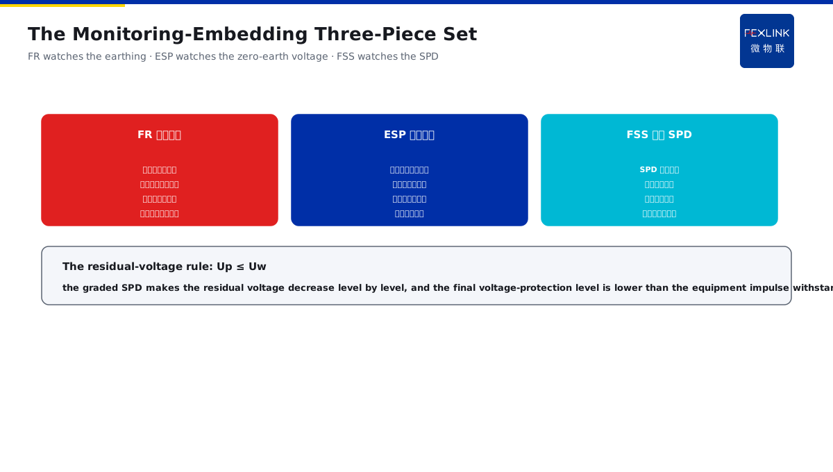
Direct Answer
For a new data center, how is the lightning protection designed as one whole from the air termination to the equipment end? The answer: design it by the "four defense lines" from top to bottom — the air termination and the down conductors (against the direct strike) → the common earthing network and the equipotential grading (lowering the earth potential) → the machine-room equipotential grids M/S (eliminating the potential difference between the equipment) → the graded power and signal SPDs (limiting the residual voltage); the four lines connect level by level, finally making the surge residual voltage at the sensitive equipment end lower than its withstand voltage.
At a new data center built by the four lines at once: the rooftop air-termination strip and the down conductors were designed per GB 50057, the underground common earthing network resistance was controlled below 1 Ω, the machine room made the equipotential grids (the M grid/S grid) per GB 50174, and the T1/T2 graded power SPDs and the signal SPDs were arranged per GB 50343; after the operation, the equipment had zero damage in the lightning season, and the monitoring system stayed online continuously. The design core: the four lines connect level by level — the air termination and the down conductors against the direct strike, the common earthing lowering the earth potential, the equipotential grid eliminating the potential difference, and the graded SPD limiting the residual voltage — each line guards its own section, finally the equipment-end residual voltage is lower than the withstand voltage, and the lightning season is worry-free.
Why:
- The direct strike is stopped first: the air termination and the down conductors;
- The earth potential is lowered first: the common earthing network;
- The potential difference is eliminated first: the equipotential grid;
- The residual voltage is limited first: the graded SPD.
Key insight: "The four lines connect level by level — the air termination and the down conductors against the direct strike, the common earthing lowering the earth potential, the equipotential grid eliminating the potential difference between the equipment, and the graded SPD limiting the residual voltage — with the design in place, the equipment-end residual voltage is surely lower than the withstand voltage."
At a data center with only the SPD installed initially and no equipotential grid, one strike caused the potential difference between the equipment to damage the network switches in batches. After the M/S-grid equipotential and the common earthing were added, the same strike left the equipment intact. Lesson: the lightning protection is a system, not a single point — only the SPD is plugging one end, and only with the four lines complete is the loop closed.
Overview: run "how the four defense lines are designed from top to bottom → how the civil engineering cooperates → how the equipotential grid and the SPD connect → how the monitoring points are embedded" as one data-center lightning design. The data-center lightning protection is designed by the four lines: the air termination and the down conductors (against the direct strike) → the common earthing network and the grading (lowering the earth potential) → the machine-room equipotential grids M/S (eliminating the potential difference) → the graded power and signal SPDs (limiting the residual voltage). The four layers are unfolded below.
A "four-flood-gates" analogy: think of the data-center lightning protection as the reservoir flood control. The lightning current is like a rainstorm flood, and one gate alone cannot stop it. The first gate is the upstream reservoir (the air termination and the down conductors, holding the flood at the source first, against the direct strike entering the room); the second gate is the spillway (the common earthing network, evenly discharging the big flood and lowering the downstream water level, against the earth-potential rise and the back-strike); the third gate is the diversion channel (the equipotential grid, balancing the water levels of the branches, against the potential difference between the equipment); the fourth gate is the end sluice (the graded SPD, controlling the last leaked water within the height the equipment can bear, limiting the residual voltage below the withstand voltage). The four gates connect level by level, and the flood (the lightning current) is reduced layer by layer to harmlessness. With one gate missing, the flood will rush in from the gap — only the SPD is like having only the end sluice, and the upstream flood still overflows the levee. The flood-control analogy: the air termination and the down conductors = the upstream reservoir holding the source, the common earthing = the spillway lowering the water level, the equipotential grid = the diversion channel balancing, and the graded SPD = the end sluice limiting the residual voltage — the four gates connect level by level, and the lightning current is reduced layer by layer to harmlessness.
1. The Design Overview: How the Four Lines Are Arranged
Step one: first look at the overview of the four data-center defense lines.
The first line:
- The air-termination strip/network;
- The down conductors evenly distributed;
- Against the direct strike entering the room;
- Completed in the civil-engineering stage.
The second line:
- The common earthing network;
- The earthing resistance below 1 Ω;
- The earth potential lowered overall;
- The back-strike risk reduced.
The third line:
- The equipotential grids M/S;
- The potential difference between the equipment eliminated;
- The lightning current discharged equipotentially;
- The equipment in the cabinet safe.
The fourth line:
- The power T1/T2 graded;
- The signal SPD matched;
- The residual voltage limited level by level;
- The equipment end below the withstand voltage.
Key insight: "The four lines each guard one section — the first against the direct strike, the second lowering the earth potential, the third eliminating the potential difference, and the fourth limiting the residual voltage — connecting level by level, and the design is a closed loop."
2. The Civil-Engineering Cooperation: The Air Termination, the Down Conductors and the Common Earthing
Step two: the civil-engineering cooperation of the air termination, the down conductors and the common earthing.
The air-termination design:
- The strip laid along the ridge;
- The grid size per GB 50057;
- The protection range covering the machine room;
- Verified by the rolling-sphere method.
The down-conductor design:
- The conductors evenly distributed;
- The spacing meeting the standard;
- Reliably connected with the strip;
- The large current discharged through multiple paths.
The common earthing:
- The foundation earthing network shared;
- The lightning/static/protective earthing united;
- The earthing-resistance target value;
- Interconnected with the equipotential grid.
Key insight: "The civil-engineering cooperation has three items — the air-termination strip covering the machine room by the rolling-sphere method, the down conductors evenly distributed and discharged through multiple paths, and the common earthing network interconnected with the equipotential — determined in the civil stage, and the structure is not changed later."
3. The Connection Points: The Equipotential Grid and the SPD
Step three: the connection between the equipotential grids M/S and the graded SPD.
The equipotential grid:
- The M grid star type, the S grid mesh;
- Arranged per GB 50174;
- Eliminating the potential difference between the equipment;
- The lightning current discharged equipotentially.
The SPD grading:
- The power T1 first-stage discharge;
- The T2 second-stage limiting;
- The signal SPD matched;
- The residual voltage decreasing level by level.
The connection key:
- The SPD earthing into the equipotential grid;
- The grid providing the low-impedance path;
- The residual voltage matched with the withstand voltage;
- The grading coordinated.
Key insight: "The connection essence — the SPD earthing must enter the equipotential grid (the grid provides the low-impedance path), the power T1/T2 and the signal SPD limit the voltage level by level (the residual voltage decreasing), and the final residual voltage is lower than the equipment withstand voltage (the matching is safe)."
4. The Monitoring Embedding: How FR/ESP/FL Are Arranged
Step four: how the monitoring points are embedded into the design.
The FR earthing monitoring:
- The common-earthing-network trend;
- The earthing-resistance drift visible;
- The grading-ring state corroborated;
- The earth-potential degradation found early.
The ESP zero-earth-voltage monitoring:
- The zero-earth voltage recorded in real time;
- The potential-difference anomaly alerted;
- The equipotential grid verified;
- The equipment safety guaranteed.
The FSS intelligent SPD monitoring:
- The SPD state online;
- The leakage trend recorded;
- The degradation replaced early;
- The graded protection verifiable.
Key insight: "The monitoring-embedding three-piece set — FR watches the earthing trend, ESP watches the zero-earth voltage, and FSS watches the SPD degradation — the state of the lightning protection after the operation is visible, and the design effect is verifiable."
5. Product Implementation: The Data-Center Lightning Closed Loop
WeiWuLian products make the data-center lightning design "verifiable and sustainable":
- FSS intelligent surge-protective device: the graded-protection state online;
- ESP zero-earth-voltage monitor: the equipotential effect verified in real time;
- FR earthing-resistance monitor: the common-earthing trend continuously watched;
- The data closed loop: the design-construction-operation fully visible.
The design principle in one sentence: "The four lines are the skeleton, and the online monitoring is the eye — FSS sees the SPD, ESP sees the zero-earth voltage, and FR sees the earthing; the effect after the operation is continuously verifiable."
6. Common Understanding Misjudgments
- "With the SPD installed, the lightning protection is done": wrong. The SPD is only the fourth line, and the first two cannot be stopped without blocking the direct strike.
- "The earthing resistance qualified is enough": wrong. The equipotential grid eliminating the potential difference is equally key.
- "The M grid or the S grid is chosen freely": wrong. It must be determined by the equipment layout and GB 50174.
- "One SPD stage is enough": wrong. Only the T1/T2 grading brings the residual voltage down.
- "No need to watch after the operation": wrong. The earthing drift and the SPD degradation must be continuously monitored.
Scope and Limitations
This article explains the four-defense-line design of the new data-center lightning protection system (the design overview, the civil-engineering cooperation, the connection points and the monitoring embedding), applicable to the data-center lightning design and retrofit. The specific design follows GB 50057-2010, GB 50343-2012 and GB 50174; this article explains only the design logic. All cases are anonymized (a data center) and do not refer to any specific customer.