 微物联研究院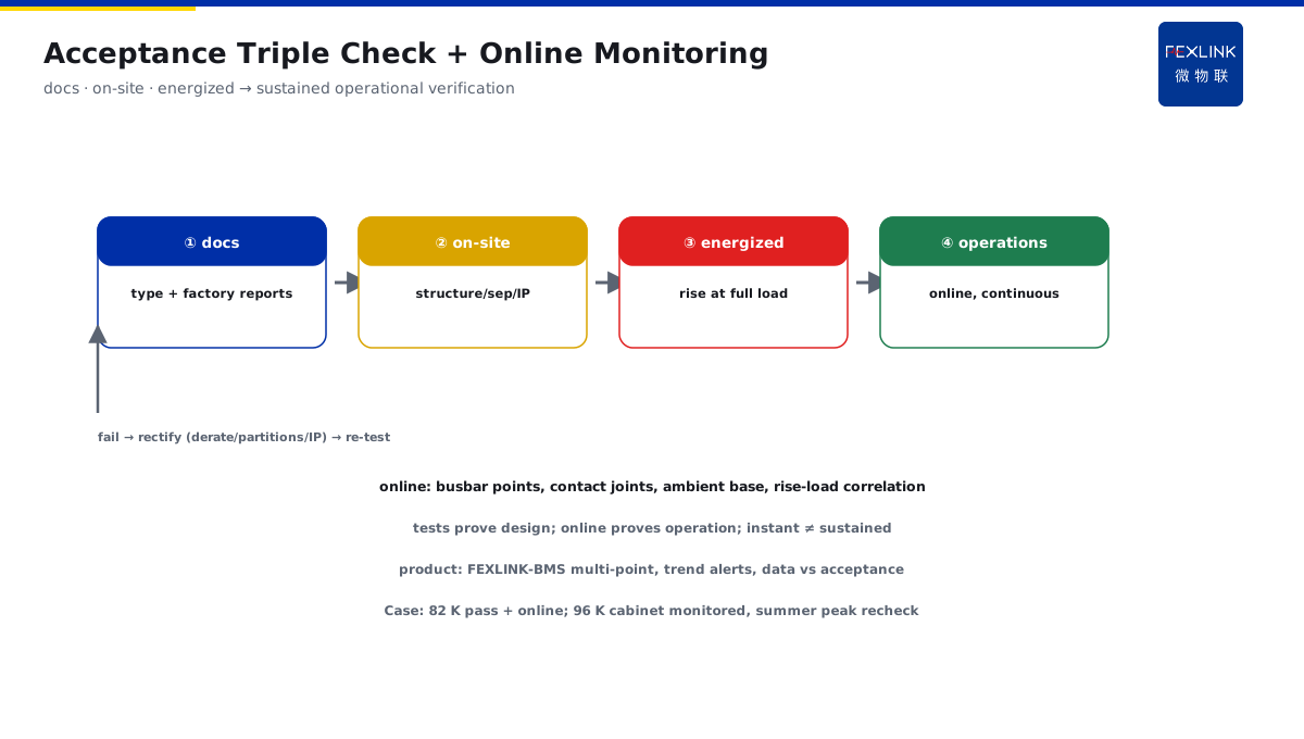
Direct Answer
During acceptance of a distribution cabinet, the owner cites standard clauses to challenge internal temperature rise and layout. How does the standard land? The answer: the GB/T 7251 series specifies temperature-rise limits, internal circuit-separation forms, and dielectric performance for low-voltage switchgear assemblies; landing at acceptance — verify that busbar and contact temperature rises do not exceed the material class, check that the internal separation form matches the design, and confirm the degree of protection; online temperature monitoring is exactly the operational-phase supplement to the temperature-rise requirement.
A plant installed a batch of LV switchgear assemblies (MNS type); during acceptance the owner cited GB/T 7251.1 to challenge busbar temperature rise. Checked against the standard: busbar material copper, temperature-rise limit 105 K at rated current (busbar temperature within 140 °C at 35 °C ambient); measured 82 K at full load on site (pass); internal separation form 3b (busbar/functional-unit/cable compartments separated); IP54 confirmed. Conclusion: acceptance passed, with a recommendation to add online temperature monitoring (continuous operational verification). The core of GB/T 7251 landing is the "temperature rise + separation + protection" triple check: busbar/contact temperature rise within the material class, internal separation form matching the design, degree of protection met — acceptance has a basis, and online monitoring supplements operation.
Because:
- Temperature rise is the safety bottom line: exceeding the limit accelerates insulation aging, contact oxidation, even faults;
- Internal separation is fault zoning: one unit's fault does not spread to other units;
- Degree of protection is environmental adaptation: dust/water protection matches the installation environment;
- Acceptance and operation are separated: tests prove design compliance, online monitoring proves sustained operational compliance.
Key insight: GB/T 7251 is the ruler for switchgear acceptance. Temperature rise + separation + protection — pass the triple check, acceptance passes; online temperature monitoring strengthens operation.
At one plant, acceptance found the busbar-compartment temperature rise high at full load (96 K, near the limit), and the owner challenged it. Rechecked per the standard: copper, limit 105 K — 96 K did not exceed but the margin was small; recommendation: add online temperature monitoring and re-verify at the summer peak — operational monitoring makes up for acceptance's "instantaneous" nature. Standard landing: acceptance measures "whether the design meets requirements," online monitoring governs "whether operation continuously meets requirements" — the two complement each other.
1. Temperature-Rise Limits in the Standard
Step one: what the temperature-rise limits are.
Temperature-rise definition:
- Temperature rise = measured temperature − ambient temperature (K);
- Ambient reference: ≤35 °C (standard condition);
- Limits per material class (copper, aluminum, plating, etc.).
Reference limits:
- Copper busbar (bare): limit 105 K (tin-plated 65 K etc. per coating);
- Contacts (silver alloy): limit 65 K;
- Busbar connections: per material and plating (60–105 K);
- Internal insulation parts: per heat class (Class F 155 °C, etc.).
Key concepts:
- The limit is "allowed temperature minus reference ambient" (not absolute temperature);
- Correction needed when ambient exceeds 35 °C (derate or assess per actuals);
- Temperature-rise test performed at rated current (type test);
- Verify at full-load conditions during acceptance.
Consequences of exceeding:
- Accelerated insulation aging (shortened life);
- Contact oxidation (higher contact resistance → hotter → vicious cycle);
- Connection loosening (thermal expansion/contraction);
- Protection misoperation (thermal elements affected by ambient).
Key insight: temperature rise is the safety bottom-line indicator. Material class sets the limit, full-load conditions verify — over limit means risk, the first acceptance check.
2. Meaning of Internal Separation Forms
Step two: how to read separation forms.
Separation forms (GB/T 7251.1):
- Form 1: no internal separation (busbar/functional units share space);
- Form 2: busbar separated from functional units;
- Form 3: busbar/functional-unit/cable compartments separated (subdivided a/b/c);
- Form 4: complete separation (busbar, functional units, cables each in independent compartments).
Meaning of separation:
- Fault zoning (one unit's fault does not spread);
- Maintenance safety (isolated maintenance without de-energizing other units);
- Protection-level coordination (separation enables protection against direct contact);
- Operational convenience (zoned maintenance).
Acceptance checks:
- Verify the separation-form annotation on the design drawings;
- On-site check that partitions/shields are complete (material, position);
- Check cable/busbar pass-through sealing;
- Confirm protection level matches the separation form.
Common non-conformities:
- Design Form 3 but missing partitions on site (downgrade);
- Partition material non-compliant (metal vs plastic);
- Cable pass-throughs unsealed (separation broken);
- Protection-level marking inconsistent with actual.
Key insight: the separation form is fault-zoning design. Form 1–4 progressive, verify partitions and sealing on site — one unit's fault does not spread, maintenance is safer.
3. On-Site Acceptance Checklist
Step three: what to check on site.
Temperature-rise checks:
- Measured busbar/contact rise at full load;
- Compare with material-class limits (copper 105 K, etc.);
- Ambient-temperature record (correct above 35 °C);
- Infrared or patch temperature verification.
Separation checks:
- Partition completeness (per designed Form);
- Cable pass-through sealing;
- Degree-of-protection confirmation (IP class);
- Marking and nameplate verification.
Degree-of-protection (IP) checks:
- First digit (dust): 5 = dust-protected, 6 = dust-tight;
- Second digit (water): 4 = splashing, 5 = jets, 7 = short immersion;
- Selection matching: indoor IP30–54, dusty environments IP5X+, humid environments raise the water digit;
- Verification method: nameplate marking + visual inspection (cable entries, door seals, vents);
- Common issues: unsealed cable entries (protection broken), aged door-seal strips, missing vent filters.
Dielectric checks:
- Insulation-resistance test (per standard);
- Withstand-voltage test (verify factory report);
- Earth continuity (effective protective circuit);
- Clearances/creepage distances (per rated voltage).
Acceptance process:
- Documentation check (type-test report, factory inspection);
- On-site inspection (structure, separation, protection);
- Energized tests (full-load temperature rise, functional tests);
- Issue acceptance records (checked item by item against the standard).
Key insight: the checklist is "three checks plus one confirmation." Temperature rise + separation + dielectric — checked item by item against the standard, acceptance has a basis.
4. Relationship Between Online Monitoring and Testing
Step four: how operation supplements.
Testing vs online monitoring:
- Type test: proves design compliance (one-off, factory);
- Factory inspection: proves each unit qualified (pre-shipment);
- Online monitoring: proves sustained operational compliance (real-time, long-term);
- The three complement each other (design → factory → operation).
Online temperature monitoring:
- Busbar temperature: multi-point measurement in the busbar compartment (hotspot monitoring);
- Contact temperature: measurement at connections (contact-resistance deterioration);
- Ambient temperature: basis for in-cabinet rise computation;
- Load correlation: rise trend vs load.
Value of online monitoring:
- Acceptance measures "instant," online measures "sustained";
- Finds operational rise deterioration (joint oxidation, loosening);
- Over-limit alerts (early action to prevent faults);
- Comparison with acceptance data (operation verifies design).
Relationship with the standard:
- Online monitoring does not replace type tests (the tests the standard requires);
- Online monitoring is the "operational landing" of the standard's rise requirement;
- Data usable for re-assessment (retrofit/capacity-increase evaluation).
Key insight: testing and online monitoring are complementary. Tests prove design, online proves operation — acceptance-pass at an instant does not equal sustained safety; monitoring covers the whole course.
5. Common Non-Conformities and Rectification
Step five: what to do when acceptance finds problems.
Common non-conformities:
- Temperature rise over limit: busbar overload / poor connections / insufficient cooling;
- Separation downgrade: missing partitions / incomplete sealing;
- Protection non-compliant: insufficient IP class (dusty/humid environments);
- Dielectric failure: insufficient clearances / damp insulation parts.
Rectification directions:
- Rise over limit: derate / strengthen cooling / check connections;
- Separation downgrade: add partitions / seal pass-throughs;
- Protection insufficient: raise the class / improve installation environment;
- Dielectric issues: treat insulation parts / dry.
Post-rectification verification:
- Re-measure temperature rise (same conditions);
- Re-check separation completeness;
- Re-test insulation/withstand;
- Issue rectification records (closed loop).
Key insight: non-conformities require closed-loop rectification. Find the problem → targeted rectification → re-test verification — complete acceptance records, basis for future operation.
6. Product Landing: Busbar Monitoring System
FEXLINK products bring the standard into operation:
- Busbar Monitoring System (FEXLINK-BMS): multi-point busbar-compartment temperature measurement (operational rise verification);
- Contact temperature: connection-point measurement (contact-deterioration detection);
- Platform analysis: rise-load correlation, trend alerts, over-limit alarms;
- Data support: operational rise data vs acceptance report (capacity-increase/retrofit evaluation).
Design principle in one sentence: turn "instant acceptance pass" into "sustained operational compliance." Standard triple check + online temperature monitoring — temperature-rise safety visible throughout.
7. Common Misconceptions in Standard Interpretation
- Temperature only, not rise: comparing absolute temperature against limits. Consequence: ambient influence ignored (misjudgment). Correct: rise = temperature − ambient, compare per limit.
- Ignoring material class: using 105 K uniformly for all locations. Consequence: misjudgment of plated/contact locations. Correct: check the corresponding limit per material and location.
- Ignoring ambient correction: no correction above 35 °C. Consequence: distorted acceptance results. Correct: correct or assess above 35 °C.
- Verify but never monitor operation: done after acceptance. Consequence: operational rise deterioration unseen. Correct: add online temperature monitoring.
- Separation on drawings only: no on-site check. Consequence: on-site downgrade unseen. Correct: dual check of drawings + site (partitions/sealing).
Scope and Limitations
This article provides a framework for landing the GB/T 7251 series for LV switchgear assemblies (temperature-rise limits, internal separation forms, acceptance checklist, online-monitoring/testing relationship, non-conformity rectification) for cabinet acceptance, in-cabinet temperature-rise challenge response, and busbar monitoring system design. Specific rise limits must be checked against the standard's clauses per cabinet type and material class; type-test and factory-inspection reports must be provided by the manufacturer; on-site acceptance tests (withstand, insulation, temperature rise) must be performed by qualified personnel per procedures. All cases are anonymized (a certain plant) and do not refer to any specific customer.