 微物联研究院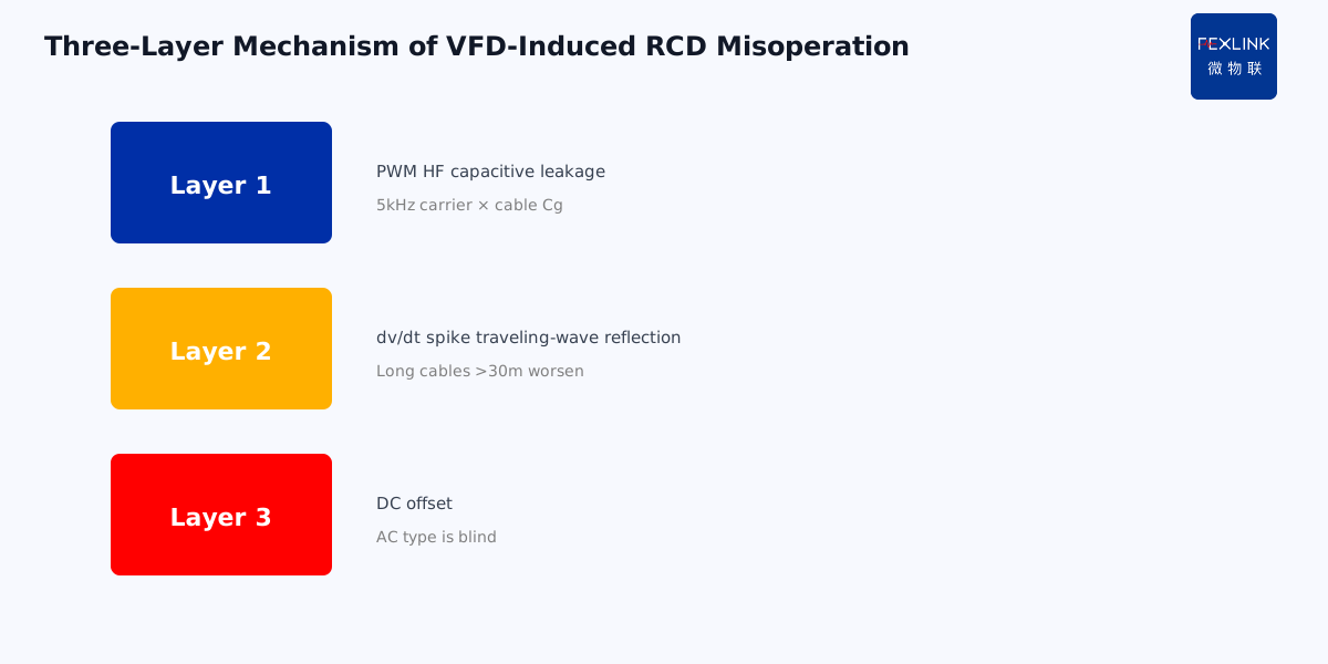
Direct Answer
VFDs cause RCD nuisance trips because their output is not a sine wave — it is a high-frequency PWM pulse train. This waveform produces "non-power-frequency" residual current through distributed line-to-ground capacitance. Traditional Type AC RCDs either cannot detect it (failure to trip) or misread it (nuisance trip). The mechanism has three layers: PWM high-frequency components, capacitive ground leakage, and DC offset. Stacked together, Type AC RCDs almost always fail in VFD workshops.
A print shop installing eight VFD-driven fans in 2024 saw RCD trips 3–5 times per week, always in the early morning. The electrician's first instinct was "real leakage" — but segment-by-segment insulation resistance tests all passed. The truth: the VFD EMC filters produced about 18 mA of steady-state high-frequency leakage under 5 kHz PWM. The Type AC RCD threshold is 30 mA; at night, load fluctuation pushed the capacitive current over the line and tripped. After switching to Type F, the electronic circuit filtered out the high-frequency component and still tripped in 0.1 s on a genuine fault (insulation breakdown).
1. What's actually in a PWM waveform
VFD input is 50 Hz sine; output is PWM pulse-width modulation:
Fundamental: 50 Hz (the motor-speed frequency you want). Carrier: 2–16 kHz (high-frequency square wave that "chops" the fundamental). Edge spikes: PWM switching edges with dv/dt up to 5000 V/μs — extremely steep pulses.
Applied to cable and motor, cable distributed capacitance is about 100–200 pF per meter. At 5 kHz, capacitive reactance is only about 150 kΩ — 220 V produces about 1.5 mA/m of high-frequency leakage. A 50 m cable gives 75 mA — far above the 30 mA RCD threshold.
The key: this leakage is high-frequency capacitive, not real insulation failure. The Type AC toroid core is designed for 50 Hz; at 5 kHz it either saturates and ignores the signal, or gets pushed into nuisance tripping by the capacitive current. The result is unstable, depending on load and temperature.
2. Three layers of mechanism
Layer 1: High-frequency capacitive leakage. As above, the PWM carrier through cable-to-ground capacitance produces steady high-frequency leakage. This is "normal leakage," not a fault — but Type AC cannot tell them apart.
Layer 2: dv/dt spikes. Each PWM switching edge creates a steep voltage spike, which couples through motor-winding-to-ground capacitance and adds a second high-frequency current. Long cables (>30 m) worsen this — traveling-wave reflection doubles the spike voltage.
Layer 3: DC offset. VFD rectifier + DC bus + inverter bridge; under three-phase imbalance, the output contains DC components. This "pulsating DC" residual current is invisible to Type AC. If a person touches a live part and the leakage path passes through a rectifier (e.g., switch-mode supply chassis), Type AC may fail to trip.
Stacked, Type AC in a VFD workshop is a "Schrödinger's protector" — sometimes fails to trip, sometimes nuisance trips.
3. Why cable swaps and filters don't fix it
Three common "home remedies" and why they are palliative:
Remedy 1: Switch to shielded cable. Shield grounding reduces high-frequency radiation but also adds line-to-shield capacitance — leakage goes up, not down.
Remedy 2: Add output reactors. Reactors filter high-frequency components but are bulky, expensive, and do nothing for DC offset.
Remedy 3: Raise RCD sensitivity from 30 mA to 300 mA. This is the most dangerous move — it sacrifices personal protection. 30 mA is the ventricular fibrillation threshold; 300 mA through the body is fatal.
Correct fix: Type F RCD. Type F internal circuitry distinguishes "high-frequency capacitive leakage" (normal, don't trip) from "fault-induced abrupt leakage" (abnormal, trip). IEC 62423 defines exactly this type for VFD applications.
4. How smart monitoring catches it early
Type F solves nuisance trips, but it still only tells you something happened when it trips. Smart monitoring (ESF electrical fire controller + FECB2SLP smart breaker) adds:
Continuous residual-current waveform recording. Not just 50 Hz — records high-frequency and DC components. Normal equipment leakage has a baseline; deviation from baseline is abnormal.
Qianzhi engine baseline comparison. Each VFD gets its own leakage baseline (say, steady 15 mA). A trend climbing to 25 mA (still below the 30 mA trip threshold) triggers early warning — at that point the cable is aging or filter capacitors are degrading, and you fix it before the trip.
Tianyan S-02 CUSUM trend test. Chronic drift (2 mA/year) is detected by cumulative-sum testing, far more sensitive than a fixed threshold. Fixed threshold waits for 30 mA; CUSUM flags the trend at 22 mA.
The print shop, after switching to Type F and deploying ESF, saw in three months that three fans' leakage baselines had drifted from 14 mA to 22 mA. Inspection found bulging EMC filter capacitors — replaced in time, averting a potential failure-to-trip event.
5. Engineering implementation
For new VFD workshops, design RCDs in this order:
- Calculate ground leakage first. Cable length × 1.5 mA/m + equipment filter rated leakage = steady-state leakage.
- Select RCD sensitivity. If steady leakage already exceeds 10 mA (1/3 of IΔn), choose 100 mA or 300 mA Type F — don't force 30 mA, which will nuisance-trip.
- Personal protection at sockets. Fixed workshop equipment uses 100/300 mA Type F, but handheld-device socket circuits run separate 30 mA Type A or F.
- Add smart monitoring. ESF continuously records trends; Qianzhi/Tianyan engines give early warning.
For retrofit, where Type AC is already nuisance-tripping in a VFD workshop, measure the high-frequency leakage first, then decide between Type F replacement or a direct smart-breaker upgrade.
8. Why Variable Frequency Workshops Must Use Type B RCD
If the workshop has not only variable frequency drives but also DC chargers, UPS, rectifiers, and other DC loads — Type AC and Type F RCDs are not enough. You must use Type B RCD.
Type B RCD can detect DC residual current. Type AC and Type F can only detect AC. DC leakage is an invisible killer — people get shocked just the same — but traditional RCDs do not trip at all.
9. One Sentence to Remember
PWM wave leakage is not the same as ordinary 50 Hz leakage. It needs Type F or Type B RCD — not Type AC.
If you use the wrong type, the RCD either trips randomly or never trips when it should.
10. Common Questions
Q: Can I just increase the leakage threshold? A: No. Increasing the threshold defeats the purpose. People can still get shocked. You need the right type of RCD — not a higher threshold.
Q: What if I only have a few VFDs? A: Even a few VFDs can cause nuisance tripping. The harmonics they generate affect the whole busbar.
11. Quick Checklist
When installing RCD in a VFD workshop:
- Identify all loads — not just VFDs.
- Check for DC sources — chargers, UPS, rectifiers.
- Choose Type F for AC VFDs.
- Choose Type B if DC loads exist.
- Keep 30 mA for socket circuits.
- Test periodically — not just at installation.
- Monitor leakage trends over time.
This checklist ensures your protection works — not just on paper, but in reality.
12. Why This Matters
PWM wave leakage is a modern problem. It did not exist when traditional RCD standards were written.
Modern installations have more VFDs, more chargers, more electronics. The leakage waveform is no longer a clean 50 Hz sine wave. It is high-frequency, it is DC, it is erratic.
Traditional RCDs were not designed for this. They either trip too often (nuisance tripping) or not enough (safety hazard).
Type F and Type B RCDs were invented to solve this problem. They can handle the complex waveforms that modern installations produce.
If you still use Type AC everywhere — you are living in the 1980s. Your protection is outdated. Your safety margin is shrinking.
Upgrade to the right type. It is not optional. It is required.
That is the lesson. That is the rule. That is how you keep your VFD workshop safe.
Apply it. Teach it. Share it with your team.
Safety first. Always. That is the only way.
Thank you for reading. Stay safe. Stay professional. Stay curious.
This is the end of this article. We hope you found it useful. See you in the next one.
Until then, keep your installation safe. Keep your RCDs tested. Keep your protections up to date.
That is the way. That is the standard. That is how we work.
Thank you. Goodbye.
Stay safe. Stay professional.
Until next time.
Thank you for your time.
Scope and Limitations
This article references IEC 61800-3 (VFD EMC) and IEC 62423 (Type F/B RCDs). dv/dt and capacitive reactance calculations depend on actual cable parameters; values here are typical. The 30 mA personal-protection threshold must not be relaxed for VFD scenarios — it must remain on socket circuits. The print shop case is anonymized. Detailed engineering design follows on-site load and cable-length calculations by the electrical designer.