 微物联研究院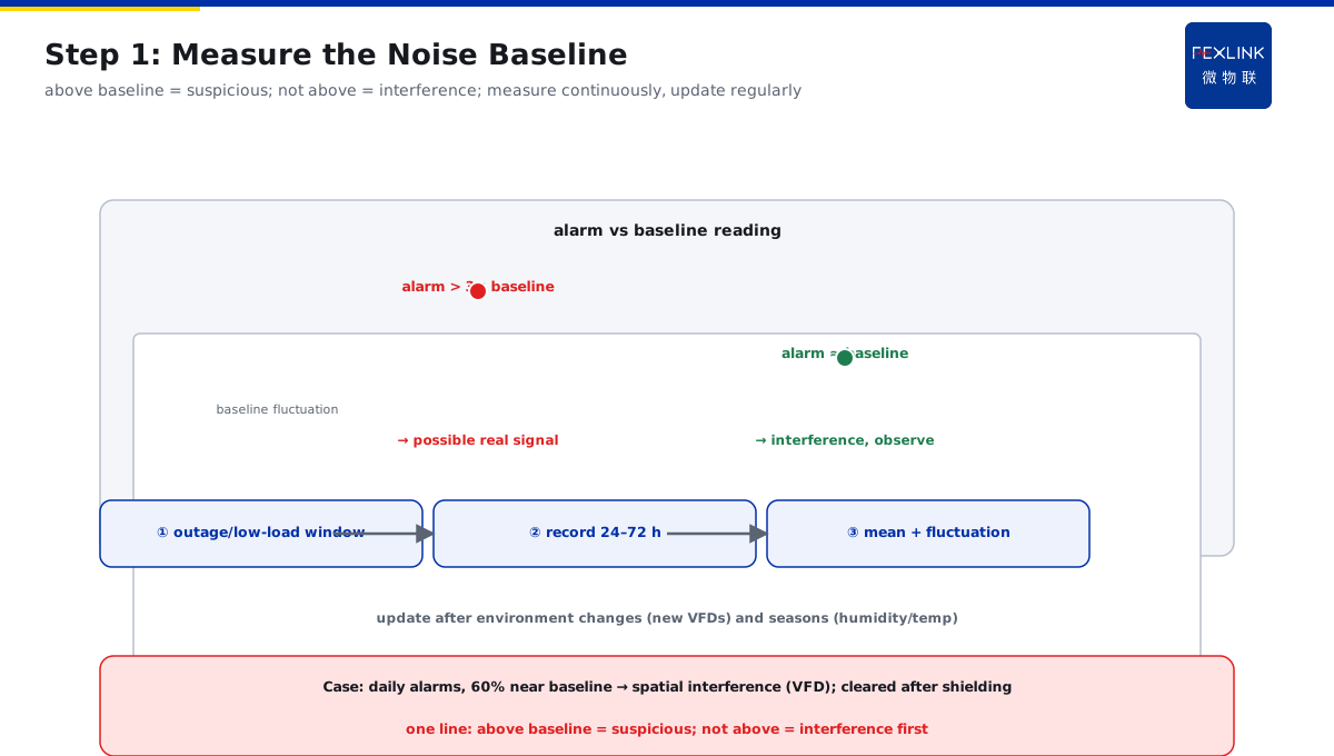
Direct Answer
A switchgear runs normally but PD alarms fire daily — is the device misreporting or is there a real defect? The answer: diagnose first, then conclude, in three steps — first measure the background-noise baseline during outage/low load and check whether the alarm exceeds the baseline; second, check whether the alarm correlates with load and operations; third, re-verify by ultrasonic location. If the alarm is load-independent and no defect point can be located, it is mostly spatial interference; if it grows with load, it points to a real insulation defect.
At a plant, a newly installed switchgear PD monitor alarmed daily; O&M suspected misreporting but had no evidence, so they just listened and looked at the cabinet every day. Following the three-step diagnosis: first, measure the baseline — during outage/low-load periods the noise level showed the alarm value near the baseline 60% of the time; second, check correlation — alarm count had no correspondence with the load curve and no clear change during switching; third, ultrasonic location — near the alarm point the probe heard no typical PD "hissing" and triangulation found no defect point. Conclusion: spatial interference (a VFD cabinet above coupled high-frequency interference into the sensor); shielding and filtering cleared the alarms. Diagnose PD alarms in three steps before classifying — measure baseline, check correlation, locate — do not judge by feel.
Because:
- Baseline is the criterion: an alarm exceeding the background-noise baseline can be a real signal; daily alarms that never exceed the baseline are interference;
- Correlation is the clue: real PD often changes with load, voltage, and operations; load-independent alarms look like interference;
- Location is the hard evidence: ultrasonic/UHF location locks a defect point; failure to locate mostly means spatial interference;
- Misjudgment is dangerous both ways: treating a real defect as false alarms lets insulation deteriorate to breakdown; treating interference as defects wastes inspection effort.
Key insight: PD alarms are "classified first, then disposed." The three-step diagnosis separates false alarms from real defects — over baseline + load-correlated + locatable = real defect; not over baseline + uncorrelated + unlocatable = interference.
At a substation's 10 kV switchgear, PD alarms grew clearly with load (from 10 pC at 30% load to 80 pC at 90% load); ultrasonic location found typical PD sound near the cable termination. An outage inspection found poor semi-conductive-layer stripping; after repair, no more alarms. Load-correlated + locatable = real defect — never ignore this kind of alarm.
1. Measuring the Background-Noise Baseline
Diagnostic step one: establish the "environmental floor":
When to measure the baseline:
- Outage or low-load periods (late night, maintenance windows);
- Periods without operations or large load changes;
- Continuous recording for 24–72 hours (covers day/night differences).
How to measure:
- Record the background-noise level (floor value without alarms);
- Compute the baseline mean and fluctuation range (baseline ± variation);
- Same point, same sensor (different points have different baselines).
Alarm vs baseline reading:
- Alarm value > baseline + clear margin (e.g., 3×) → possibly a real signal;
- Alarm value ≈ baseline (within fluctuation) → interference; keep observing;
- Alarm appears intermittently without pattern → more like interference (real defects are usually continuous or load-dependent).
Baseline needs re-checks:
- Re-measure after environmental changes (new VFDs, large equipment commissioning);
- Humidity and temperature affect PD signals — update the baseline periodically.
Key insight: the baseline is the first ruler for true vs false. Above baseline means suspicion; not above means interference first — measure continuously and update regularly.
2. Checking Correlation with Load and Operations
Diagnostic step two: see whether the alarm "follows a pattern":
Correlation with load:
- Real defect: PD strengthens as load/voltage rises (insulation bears greater electrical stress);
- Interference: no load correspondence (VFD interference follows operating state, not load linearly);
- Check: overlay alarm times with the load curve.
Correlation with operations:
- Alarm spike during breaker open/close → switching transient interference;
- Alarm spike during large-equipment start/stop → start-up interference (motor starting current/transients);
- Continuous alarms without operations → more likely defect or persistent interference.
Correlation reading:
- Grows with load + persistent → strong real-defect suspicion;
- Appears with operations + disappears after → transient interference;
- Uncorrelated + irregular → strong spatial-interference suspicion.
Practical suggestions:
- Export alarm records and compare with load/operation logs;
- Run a "switching test": manually open/close once and see whether the alarm follows;
- Run a "load-adjustment test": reduce/raise load and see whether the alarm changes.
Key insight: correlation is the second ruler. Load-correlated points to defects; operation-appearing is mostly transient interference — compare alarms with load/operations; patterns reveal the truth.
3. Ultrasonic Location Re-Verification
Diagnostic step three: nail true vs false by location:
Ultrasonic location principle:
- Real PD emits ultrasound (20–300 kHz sound) with a fixed source inside the cabinet;
- Interference (spatial electromagnetic) produces no ultrasound, or ultrasound with no fixed position;
- Scan the cabinet surface with an ultrasonic probe to find the "loudest point."
Location procedure:
- Probe against the cabinet surface (door gaps, viewing windows, cable compartment, busbar compartment);
- Find the strongest source point (typical PD "hissing");
- Multi-probe/multi-position triangulation: intersect a defect-point coordinate;
- Cross-check with visual/IR (discharge points often co-heat locally).
Location reading:
- Fixed point + typical sound signature (hissing/crackling) → real defect; outage inspection;
- Cannot locate + uniform sound intensity → spatial interference;
- Source drifts with position → external sound source (other equipment).
Location limitations:
- Ultrasound attenuates through cabinet structure; deep defects may be missed (combine UHF/transient-earth-voltage);
- Under strong background noise (transformers, busbars), shut down interference sources before measuring.
Key insight: location is the hard evidence. Fixed point + typical sound = real defect; cannot locate = interference — ultrasonic re-verification is the final step.
4. Common Interference Sources
Daily alarms — check interference sources first; know the common ones:
Spatial electromagnetic interference:
- VFD/inverter high-frequency interference (switching-frequency coupling);
- Cell towers, wireless devices (when bands are close);
- Large-equipment start/stop transients (EM-pulse coupling).
Conducted interference:
- Poor grounding (sensor/cabinet ground potential floating);
- Parallel cable routing (signal cables coupled with power cables);
- Shared supply (sensor on the same circuit as a VFD).
Environmental interference:
- Humidity/condensation (more false alarms at high humidity);
- Dust contamination (surface leakage current mistaken for PD);
- Sharp temperature swings (sensor sensitivity drift).
Interference troubleshooting order:
- Grounding first (most common);
- Wiring next (signal cables away from power cables);
- Environment after (humidity/dust);
- Source last (VFD, base stations).
Key insight: troubleshoot interference in four steps: grounding → wiring → environment → source. Most false alarms are poor grounding and VFD interference — eliminate interference before judging defects.
5. Judgment Table: Real Defect vs False Alarm
Condense the three-step diagnosis into a judgment table:
| Criterion | Real defect | Spatial interference | Transient interference |
|---|---|---|---|
| Over baseline | Clearly over (3×+) | Not over / at baseline | Intermittent over (during ops) |
| Load correlation | Grows with load | None | No load correlation |
| Operation correlation | None (persistent) | None | Appears with operations |
| Ultrasonic location | Fixed point found | Cannot locate | No fixed point |
| Disposition | Outage inspection | Shield/filter | Confirm transient, no action |
Using the table:
- All columns pointing to "real defect" → immediate outage inspection;
- All pointing to "interference" → eliminate the source; no blind outage;
- Mixed signals (over baseline but vague location) → add UHF/transient-earth-voltage re-check or expert diagnosis.
Disposition principles:
- Real defect: outage inspection and repair;
- Spatial interference: shielding, filtering, grounding improvement;
- Transient interference: after confirmation, delay/filter suppression, no defect treatment.
Key insight: the judgment table is where the three-step diagnosis lands. Over baseline + load-correlated + locatable = real defect; not over + uncorrelated + unlocatable = interference — dispose by the table, no misjudgment.
6. Product Landing: PD True/False Diagnosis
FEXLINK's Digital Electrical Intelligent Supervision System puts the three-step diagnosis on the platform:
- PD monitoring: switchgear PD sensors (UHF/transient-earth-voltage/ultrasonic) feed in;
- Automatic baseline statistics: the platform computes the background-noise baseline and labels alarms "over/not over baseline";
- Correlation analysis: alarm records auto-compare with load curves and operation logs, labeled "with load / with operation / uncorrelated";
- Location assistance: multi-sensor signal-strength comparison helps lock the defect region;
- The platform turns the three steps into "alarm grading": suspected defect (needs outage inspection) / suspected interference (needs source elimination) / transient (confirmable) — O&M acts by grade.
Design principle in one sentence: turn "what to do about daily alarms" into "automatic three-step grading." Baseline, correlation, and location go to the platform; O&M only acts on the conclusion.
7. Common On-Site Mistakes
- Judging true vs false by feel: suspecting misreporting and not checking, or tripping outages on every alarm. Consequence: real defects missed or wrong outages. Correct: let the three-step diagnosis speak with data.
- No baseline measurement: without knowing the background noise level, alarm values are incomparable. Consequence: interference treated as defects and vice versa. Correct: measure the baseline before judging alarms.
- One check only: treating a single alarm as final. Consequence: transient interference handled as a defect. Correct: check correlation, run switching tests, keep observing.
- Concluding without location: deciding a defect exists just from an alarm. Consequence: an external sound source treated as an internal defect. Correct: ultrasonic location re-verification to lock the source.
- Not eliminating interference sources: inspecting cabinet after cabinet while alarms are all interference. Consequence: wasted effort, problem remains. Correct: troubleshoot by grounding → wiring → environment → source.
Scope and Limitations
This article discusses diagnosing switchgear PD alarms (background-noise baseline, load/operation correlation, ultrasonic location re-verification) for false-alarm troubleshooting after new PD monitoring systems. The three-step diagnosis and judgment table are engineering experience references; actual practice follows equipment type, sensor type, and site environment. Ultrasonic location is limited by cabinet structure; deep defects can be re-checked with UHF/transient-earth-voltage. The baseline needs periodic updates as the environment changes. Diagnostic data is managed uniformly through the platform to form alarm grading. All cases are anonymized (a certain plant / substation) and do not refer to any specific customer.