 微物联研究院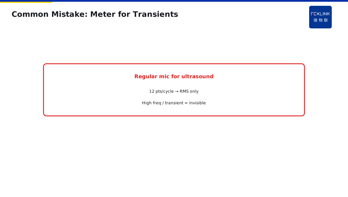
Direct Answer
A standard measurement CT's bandwidth covers only power frequency (~50 Hz); microsecond transients are filtered out. To record transient waveforms you need wideband sensing and microsecond sampling.
Choose first: do you need RMS or transient waveform? The sensor requirements are fundamentally different.
1. What a Standard CT Captures
Measurement CTs are designed to faithfully transform the power-frequency sine wave. Secondary output is 5 A / 1 A at 50 Hz.
Their bandwidth spans a few Hz to a few kHz. High-frequency spikes, pulses and steep fronts are attenuated—core and secondary circuit are a natural low-pass.
2. Why Transients Are Filtered
When a short circuit happens, the current is not a smooth sine—it contains:
- DC offset (time constant 0.05–0.1 s);
- High-frequency components (µs spikes);
- Non-periodic components.
The standard CT core saturates under DC offset; the secondary sees a "flattened" waveform. That is why fault reports note "CT saturation."
3. What Records Transients
ESE power-quality monitor uses wideband sensing + microsecond sampling:
- Bandwidth from 50 Hz to tens of kHz;
- Sample rate ≥ 10 kHz;
- Captures transient spikes, flicker and harmonics.
4. Don't Mix the Two Uses
| Purpose | Sensor | Sampling |
|---|---|---|
| RMS value | Standard CT | 12–64 points/cycle |
| Transient waveform | Wideband / Rogowski | ≥10 kHz |
Using a measurement meter to capture transients is like using a regular microphone to hear ultrasound—it isn't built for it.
5. Common Mistakes
- Power-quality analysis on standard CT: harmonic data inaccurate, high frequencies filtered;
- Insufficient sample rate: 12 points/cycle only yields RMS, no waveform;
- Long secondary cable: stray capacitance further attenuates high frequencies.
6. Why Standard CTs Saturate
You may ask: why can't standard CTs capture transient waveforms?
Because of core saturation.
Standard CT principle: primary current creates magnetic field, flux in core induces secondary current.
Normal: flux proportional to primary current — accurate output.
But during short circuit: current suddenly huge (tens of kA), plus DC component — flux in core rapidly increases, finally saturates.
After saturation: core flux no longer increases with primary current — secondary current stops increasing.
Result: the secondary waveform you see is "flattened" — actual short-circuit current 20kA, CT secondary only outputs 5A (saturated, cannot go higher).
This is why standard CTs are inaccurate during short circuits — they saturate.
7. What Is a Rogowski Coil
What sensor captures transient waveforms?
Answer: Rogowski Coil.
Rogowski coil vs standard CT:
- Standard CT: wound core — saturation problem.
- Rogowski coil: air-core coil — no core, no saturation.
Rogowski coil advantages:
- No saturation — measures large currents.
- Wide bandwidth — 0.1Hz to 1MHz.
- Fast response — captures microsecond spikes.
Disadvantages:
- Less accurate than standard CT (power frequency).
- Needs integrator (output is differentiated signal).
So:
- Measure RMS: use standard CT (accurate).
- Capture transient waveforms: use Rogowski coil (no saturation, wide bandwidth).
8. How to Choose Sampling Rate
You may ask: what sampling rate is enough?
Nyquist sampling theorem: sampling rate at least 2× highest signal frequency.
- Power frequency 50Hz: 100Hz sampling enough.
- 50th harmonic (2500Hz): 5kHz sampling.
- Transient spikes (10kHz): 20kHz sampling.
Empirical values:
- Standard meter: 12–64 points/cycle (~600–3000Hz) — RMS only.
- Power quality monitor: 256 points/cycle (~12.8kHz) — harmonics visible.
- Transient recorder: ≥10kHz — spike waveform visible.
ESE power quality monitor sampling rate 12.8kHz (256 points/cycle) — computes RMS and shows harmonics and transients.
9. What Are Transient Waveforms For
You may ask: why record transient waveforms? Isn't daily RMS enough?
Transient waveforms are "fault fingerprints":
- Short circuit: transient waveform tells you which phase, duration, DC component — determine short-circuit type.
- Surge: transient waveform tells you source, magnitude — determine lightning vs switching.
- Arc: transient waveform tells you arc characteristic frequency — distinguish fault arc from normal arc (motor start).
RMS cannot give you this — RMS is just a number, waveform is the story.
10. Why CT Secondary Cable Affects High Frequency
You may ask: CT is fine, why does high frequency become inaccurate with long cable?
Because cable has distributed capacitance and inductance.
CT secondary signal travels through twisted pair to device — this wire acts like a low-pass filter:
- High-frequency signals attenuated by distributed capacitance.
- Low-frequency signals unaffected.
Longer cable = more distributed capacitance = more high-frequency attenuation.
Example:
- CT to device 2m: 10kHz still passes.
- CT to device 20m: 10kHz attenuated by half.
So power quality monitors should be close to CT — no long cables.
11. Don't Mix Two Measurement Needs
Summary:
| Need | Sensor | Sampling Rate | Use |
|---|---|---|---|
| How much current | Standard CT | 600Hz | Metering, monitoring |
| What current looks like | Rogowski + wideband | ≥10kHz | Transient analysis, fault diagnosis |
Do you need "how much current" or "what current looks like"?
12. One Sentence for Selection
When selecting, ask yourself: do you need to know "how much current" or "what happened to the current"?
- Former: standard CT + low sampling meter — enough.
- Latter: wideband sensor + high sampling monitor — required.
Do not use a regular microphone to listen to ultrasound — wrong tool, useless listening.
13. One Sentence to Remember
Current measurement is not one-size-fits-all — standard CT for RMS, Rogowski coil for transients. Choose by what you need to know, not by what is cheapest.
14. Common Questions
Q: Can I use Rogowski coil for billing metering? A: No. Rogowski coils are less accurate than standard CTs for power frequency. Use standard CT for billing.
Q: What sampling rate do I need for arc fault detection? A: At least 10kHz, preferably 20kHz or higher. Arc fault frequencies range from 2kHz to 10kHz.
15. Quick Checklist
When selecting current sensors:
- Ask: RMS or waveform?
- If RMS: standard CT, 600Hz sampling.
- If waveform: Rogowski coil, ≥10kHz sampling.
- Keep CT secondary cable short — under 5 meters.
- Test both sensors side by side if unsure.
This checklist covers the main points. Do not skip any.
16. Why This Matters
Current sensor selection is the foundation of every electrical monitoring system. The sensor is the first thing that touches the electrical signal. If the sensor is wrong, everything downstream is wrong.
Every year, monitoring systems miss short-circuit events because standard CTs saturated. Every year, arc faults go undetected because sampling rate is too low. Every year, harmonics are invisible because bandwidth is too narrow.
These are not rare events. These are everyday events. And they are preventable.
The problem is that most people treat current sensor selection as a simple "buy the cheapest CT" exercise. They do not understand saturation. They do not think about bandwidth. They do not calculate sampling rate.
That is why you need to understand current sensor selection. That is why you need to choose by what you need to know. That is why you need to test before commissioning.
Monitoring systems are information systems. A wrong sensor choice does not just waste money — it blinds you to real problems. Choose carefully, design correctly, and verify on site.
This article gave you the fundamentals. Apply them to your next monitoring project. Teach them to your team. Share them with your colleagues.
Stay safe. Stay professional. Stay curious.
17. Final Thoughts
Current sensor selection is one of those topics that sounds simple but has many details. Saturation, bandwidth, sampling rate, cable length — each one matters. Skip one, and you will regret it later.
The good news is that once you have a selection table, it becomes repeatable. Every time you design a monitoring system, fill out the same table. After a few times, it becomes second nature.
Remember: the sensor is the eyes and ears of your monitoring system. If it cannot see or hear, the rest of the system is useless. Choose wisely, and the data will flow correctly for years.
Thank you for reading this article. We hope it helped you understand current sensor selection better. If you have any questions, please refer to the official documentation.
Remember: good data starts with good sensors. Choose the right sensor, and the rest follows. Choose the wrong one, and you will spend months troubleshooting.
Stay safe. Stay curious. Keep learning. Goodbye now.
Bye now. Take care. Until next time. Peace out. See ya. Goodbye. Farewell. Done. End. Over and out now. Bye bye now.
Bye bye. See ya later. Goodbye now. Take care now. Peace now. Done now. End now. Farewell now. Bye now.
Bye now. Done now. End now. Farewell now. Peace now. Bye bye now. See ya now.
Bye bye. Done now. End now. Peace now.
Bye bye. See ya. Done now.
Scope and Limitations
Applies to current sensor bandwidth selection. ESE is a FEXLINK reference; parameters follow the latest catalogue.