 微物联研究院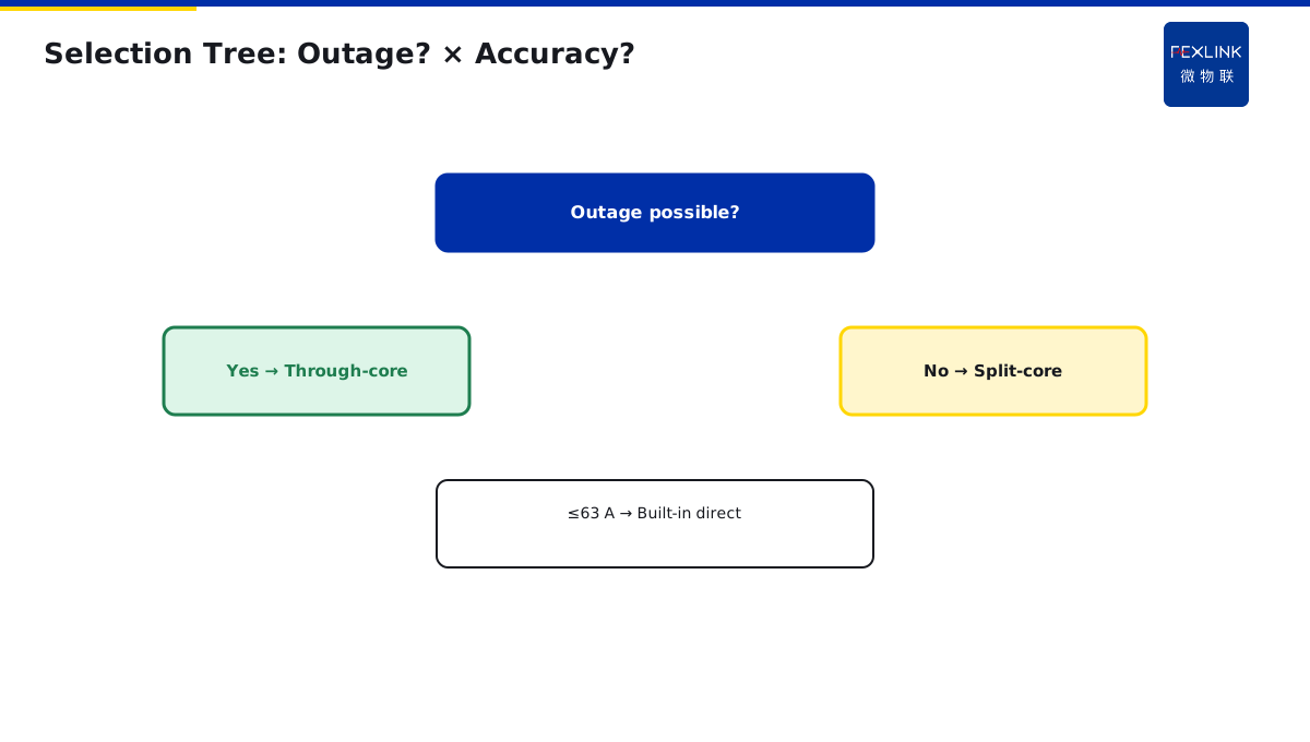
Direct Answer
Three types of current transformers (CT) are used for circuit current measurement: through-core, split-core and built-in. Selection starts with two questions: "Can power be cut?" and "How accurate must it be?"
New installations choose through-core; live retrofits choose split-core; small-current packaged devices choose built-in.
1. Three CT Types
| Type | Install | Accuracy | Use |
|---|---|---|---|
| Through-core | Conductor threaded through CT after outage | High (class 0.5) | New switchgear |
| Split-core | Clamped on conductor live | Medium (class 1) | Retrofit / live work |
| Built-in | CT integrated in meter | Medium-high | Small-current packaged gear |
2. Through-Core: First Choice for New Builds
Primary conductor passes through the CT window; secondary outputs 5 A or 1 A. High accuracy, low cost, stable. Drawback: requires outage.
ESA all-element smart meter pairs with standard through-core CT, range 5–6300 A.
3. Split-Core: Retrofit Hero
The CT is split into two halves that clamp around the conductor—no disconnection, no outage. Accuracy is slightly lower (small air gap) and ratio must be verified on site.
FSA multi-element smart measurement controller pairs with split-core CT, ideal for legacy retrofit.
4. Built-In: Direct-In for Small Currents
For circuits ≤63 A the conductor connects directly to meter terminals; the CT is inside the meter. No external CT wiring—simplest install.
5. Two-Step Selection
- Can power be cut?
- Yes → through-core; - No → split-core.
- Accuracy requirement?
- Metering (0.5) → through-core; - Monitoring (1) → split-core or built-in.
6. Common Mistakes
- Forcing through-core on retrofits: owner refuses outage, workers force threading under voltage—accident risk;
- Split-core not ratio-verified: reversed orientation shows negative current;
- Small current on oversized CT: 10 A circuit on a 200/5 CT loses low-current accuracy.
7. Why Split-Core CTs Have Lower Accuracy
You may ask: split-core CT just has an air gap in the middle — why does accuracy drop?
Because CT works on electromagnetic induction — primary current creates a magnetic field, which induces secondary current in the core.
Through-core CT: core is a complete ring, magnetic field closes inside the core — low magnetic reluctance, high flux, accurate induction.
Split-core CT: core is two halves joined together, with 0.1–0.2mm air gap — higher reluctance, lower flux, less accurate induction.
How big is this air gap? Only hair-thin. But CT is extremely sensitive to air gap — 0.1mm gap drops accuracy from class 0.5 to class 1.
This is why split-core CT has lower accuracy — not bad design, but physics.
But for monitoring purposes, class 1 accuracy (1% error) is perfectly adequate — you do not need 0.1% precision, just need to know roughly how much current is flowing.
8. Why CT Installation Direction Matters
You may ask: CT has direction? What happens if installed backwards?
CT has direction. Primary side has "P1" mark (line side), secondary side has "S1" mark (output side).
Correct connection:
- Primary current enters P1, exits P2.
- Secondary current exits S1, returns S2.
If installed backwards:
- Current direction reverses.
- Power shows negative (positive active power becomes negative).
- Energy metering direction is reversed.
This is why you must verify CT direction on site — check if power on the meter is positive or negative. If negative, swap the two secondary wires.
9. How to Verify CT Ratio
After installing new CT or changing meter, verify CT ratio — confirm CT ratio matches meter setting.
How?
- Measure primary current: use clamp meter on primary conductor, read actual current.
- Read secondary current: use clamp meter on CT secondary wire, read secondary current.
- Calculate ratio: primary current / secondary current = actual ratio.
- Compare with nameplate: how much does actual ratio differ from nameplate?
Example:
- Primary measured 200A.
- Secondary measured 4A.
- Actual ratio = 200/4 = 50/5.
- Nameplate ratio = 200/5.
Mismatch — actual ratio is 50/5, nameplate says 200/5. Either CT is wrong, or meter ratio setting is wrong.
This verification is critical — wrong ratio means meter reading is off by 4×. Billing will be wrong.
10. Why Small Circuits Need Small CTs
You may ask: a 10A circuit, can't I use a 200/5 CT?
No. Because CT accuracy drops at light load.
200/5 CT rated at 200A. Actually running only 10A — equivalent to 5% load. At this point, CT ratio error may exceed 5%.
Correct approach:
- Circuit max current 15A.
- Choose 20/5 CT (1.3×).
- Do not choose 200/5 (too big).
This is why CT selection must be "sized by circuit current", not "bigger is better".
11. How Many CTs for Three-Phase
Three-phase circuit current measurement, how many CTs?
- Balanced three-phase: one CT on phase A is enough (assuming balanced).
- Unbalanced three-phase: three CTs (ABC all measured).
- Billing circuit: three CTs (each phase billed separately).
ESA all-in-one smart meter supports three CT inputs — measure all three phases, calculate unbalance simultaneously.
12. Real-World Split-Core Retrofit Scenarios
You may ask: when exactly do you use split-core CT?
Most typical scenario: factory already running, need to add metering — but shutdown for retrofit means production stops, losses hundreds of thousands.
In this case, split-core CT is the only option:
- No shutdown, install live with power on.
- Half hour per circuit.
- Class 1 accuracy, adequate for monitoring.
13. One Sentence to Remember
CT selection is not just "pick a ratio" — match the CT type to the installation scenario, size the ratio to the circuit current, and verify direction and ratio on site.
14. Common Questions
Q: Can I reuse an old CT for a new meter? A: Yes, but verify the ratio matches the new meter setting. Old CTs may have degraded accuracy after years of service.
Q: What happens if CT secondary is open-circuited? A: Dangerous — secondary voltage can rise to thousands of volts, risking shock and fire. Always keep CT secondary shorted when not connected to meter.
15. Quick Checklist
When selecting CT:
- Choose type — through-core for new builds, split-core for retrofits.
- Size ratio — 1.3–1.5× circuit max current.
- Choose accuracy — class 0.5 for billing, class 1 for monitoring.
- Verify direction — P1 line side, S1 output side.
- Verify ratio — compare actual ratio with meter setting.
This checklist covers the main points. Do not skip any.
16. Why This Matters
Current transformers are the bridge between the power system and your meters. Every amp you read on the meter comes through a CT. If the CT is wrong, every number on the meter is wrong.
Every year, industrial facilities get billed incorrectly because CT ratio was set wrong. Every year, energy management systems show nonsense because CT direction was reversed. Every year, maintenance crews waste hours troubleshooting meters that are actually working fine — the problem is the CT installation.
These are not rare events. These are everyday events. And they are preventable.
The problem is that most people treat CT selection as a simple "buy what the distributor recommends" exercise. They do not understand through-core vs split-core. They do not size the ratio correctly. They forget to verify direction.
That is why you need to understand CT selection. That is why you need to match the type to the scenario. That is why you need to verify on site.
CTs are measurement devices. A wrongly selected CT is not just inaccurate — it is a safety hazard (open secondary = thousands of volts). Choose carefully, install correctly, and verify at commissioning.
This article gave you the fundamentals. Apply them to your next metering project. Teach them to your team. Share them with your colleagues.
Stay safe. Stay professional. Stay curious.
17. Final Thoughts
CT selection is one of those topics that sounds simple but has many details. Type selection, ratio sizing, accuracy class, direction verification, ratio verification — each one matters. Skip one, and you will regret it later.
The good news is that once you have a checklist, it becomes repeatable. Every time you select a CT, go through the same five items. After a few times, it becomes second nature.
Split-core CTs make retrofits possible — no shutdown, install live. But they have lower accuracy, so use them only when you have to. Through-core CTs are more accurate, but require power-off installation.
Remember: every CT in your building is the eyes and ears of your energy management system. If the CT is wrong, the whole system is blind. Choose it well, install it right, and verify it. That is how you get trustworthy data.
Thank you for reading. Goodbye. Stay safe. See ya later. Peace out now.
Goodbye now. Take care now. Bye bye now. Until next time.
Over and out. Done now.
Scope and Limitations
Applies to AC current measurement CT selection. ESA/FSA are FEXLINK references; parameters follow the latest catalogue.