 微物联研究院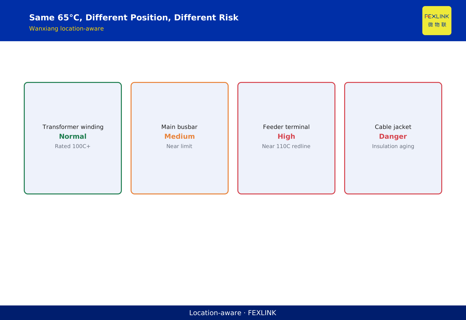
Direct Answer
Contact resistance is the extra resistance from current constriction at a bolted joint's microscopic contact points. 0.1 mΩ on a 1000 A circuit dissipates 100 W—a coffee-cup-sized joint heating like a desk lamp. This is why "a few tenths of a milliohm" decides the thermal rise of an entire cabinet.
At a factory LV room, an 800 A transformer feeder. Infrared caught a busbar lap joint rising from 35°C ambient to 78°C. Offline micro-ohmmeter read 0.18 mΩ. At 800 A: P = 800² × 0.00018 = 115 W. One joint, 115 W continuous heat—no wonder the cabinet ran hot.
1. Where Contact Resistance Comes From
Copper bars look tightly bolted, but actual contact area is only 1–5% of the macro area—surface roughness leaves only peaks touching. Current constricts through these tiny asperities ("constriction resistance"), plus an "oxide film resistance" on the surface.
Key traits:
- Non-linear: more pressure → more asperities touch → lower R, until saturation.
- Time drift: fretting corrosion and oxide film raise R year over year.
- Position-sensitive: the same R on a main bus vs. a feeder terminal carries very different risk.
2. Why 0.1 mΩ Drives Thermal Rise
Heating power: P = I²R.
| Current | R=0.05 mΩ | R=0.1 mΩ | R=0.5 mΩ |
|---|---|---|---|
| 100 A | 0.5 W | 1 W | 5 W |
| 400 A | 8 W | 16 W | 80 W |
| 800 A | 32 W | 64 W | 320 W |
| 1000 A | 50 W | 100 W | 500 W |
On high-current circuits, a 0.1 mΩ delta is tens to hundreds of watts. This is why GB/T 7251 sets separate limits for busbars, terminals, and contacts—different current density.
3. GB/T 7251 Thermal Rise Limits
| Location | Ambient | Rise allowed |
|---|---|---|
| Busbar connection | 40°C | 70 K (≤110°C) |
| Line terminal | 40°C | 70 K |
| Breaker internal contact | 40°C | Per device standard |
| Touchable enclosure | 40°C | 25 K (metal) / 40 K (insulated) |
FEXLINK Wanxiang engine's location-aware logic directly applies: the same 65°C means:
- Transformer winding = normal (rated for 100°C+)
- Main busbar = moderate risk
- Feeder terminal = high risk (near 110°C red line)
- Cable jacket = dangerous (insulation aging accelerates)
4. How to Measure Contact Resistance
Offline micro-ohmmeter: most accurate, but requires shutdown and disassembly. Reads the absolute value "right now."
Online temperature inference: no shutdown, use the FEXLINK EST multi-channel temperature monitor with NTC sensors stuck on joints, reporting real-time temperature. Higher temperature → infer higher R. But temperature sees the "result," not the absolute R.
The EST-22920-R supports LoRa wireless temperature, up to 100 channels, 1-minute sampling, ≤300 m range. Retrofit on old cabinets needs no drilling, no wiring—sensors stick to busbar laps, data goes back via LoRa to the gateway.
5. How AI Uses Temperature to Infer Contact Resistance
Absolute temperature alone is not enough—the trend matters. The Qianzhi engine M03 (temperature sub-model) applies location-aware correction—the same 65°C weighs differently by position. The Tianyan engine S-02 (CUSUM trend drift) detects mean drift over 30 days before the red line, warning 4–12 weeks ahead: this joint's R is climbing, schedule cleanup at next shutdown.
Post-event EST review of that 78°C joint showed: temperature started slope-rising from 40°C thirty days earlier; CUSUM should have alarmed at 50°C—but the system was not online yet.
6. Why Contact Resistance Grows Over Time
A reader may ask: contact resistance is very small when new — why does it grow after a few years?
Because of fretting corrosion (see KD-0053):
Year 1:
- Clean contact surface — thin oxide film.
- Contact resistance 20 μΩ.
- Normal temperature.
Year 2:
- Micro-movement scrapes oxide film — new oxide film is thicker.
- Contact resistance 50 μΩ.
- Temperature starts rising.
Year 3:
- Oxide film gets thicker and thicker.
- Contact resistance 150 μΩ.
- Temperature is noticeably high.
This is contact resistance drift over time — not the bolt loosened, but the oxide film thickened.
7. How to Lower Contact Resistance
How do you lower contact resistance?
Three methods:
1. Increase pressure:
- Higher bolt torque.
- More contact points.
- Lower contact resistance.
But pressure saturates at a certain level — more torque does not help.
2. Increase contact area:
- Larger busbar contact surface.
- More contact points.
- Lower contact resistance.
3. Apply conductive grease:
- Blocks air.
- Prevents oxide film from regenerating.
- Stabilizes contact resistance.
Combine all three methods — do it right at installation — contact resistance stays low for 5+ years.
8. A Real Case
A factory low-voltage distribution room — transformer outgoing circuit 800 A.
Infrared inspection found main busbar joint temperature rose from 35°C to 78°C.
Power-off micro-ohmmeter measurement — contact resistance 0.18 mΩ.
Heat calculation: P = 800² × 0.00018 = 115 W.
One joint dissipating 115 W continuously — cabinet temperature cannot come down.
Treatment:
- Open the joint.
- Remove oxide film with fine sandpaper.
- Apply conductive grease.
- Re-torque per process.
After re-energizing — temperature returned to 45°C.
Lesson: 0.18 mΩ sounds tiny — but at 800 A it is 115 W — the heat of a desk lamp.
Correct approach: EST wireless temperature monitoring — real-time trend tracking — detect contact resistance climb early.
9. One Sentence to Remember
Contact resistance is invisible — but its heat is visible on the temperature sensor. 0.1 mΩ at 800 A is 64 W — enough to overheat a joint.
Track the temperature trend. Detect the resistance climb. Fix it before it burns.
10. Common Questions
Q: Is 0.1 mΩ a lot or a little? A: It depends on the current. At 100 A it is only 1 W — negligible. At 1000 A it is 100 W — significant heat. Always calculate P = I²R.
Q: Does tightening the screw lower contact resistance? A: Only partly. It increases macro pressure — but the microscopic oxide film is still there. You must open the joint, remove the oxide film, and apply conductive grease.
11. How EST Wireless Temperature Helps
The EST wireless temperature sensor mounts directly on the busbar joint. It reports temperature in real time — every few seconds.
The 天衍 CUSUM engine tracks the temperature trend. If the slope starts rising — even if the absolute temperature is still below the alarm threshold — it flags it as an early warning.
This gives you weeks or months of advance notice. You can schedule maintenance during a planned shutdown — not during an emergency.
12. Quick Checklist
When you see a hot busbar joint:
- Calculate P = I²R — how much heat is being generated.
- Measure contact resistance with a micro-ohmmeter.
- If resistance is high, open the joint.
- Remove the oxide film.
- Apply conductive grease.
- Re-torque per process.
- Install EST wireless temperature monitoring.
This checklist ensures you fix the real problem — not just the symptom.
13. Why This Matters
Contact resistance is one of the most common causes of electrical fires. It starts small — a few micro-ohms — and grows slowly over years. By the time you see smoke, it is already too late.
Online temperature monitoring catches it early. The trend tells you something is wrong — long before the absolute temperature reaches the danger zone.
That is the value of predictive maintenance. That is the value of data.
That is the lesson. That is the rule. That is how you keep your busbar joints safe for decades.
Apply it. Teach it. Share it with your team.
Safety first. Always. That is the only way.
Thank you for reading. Stay safe. Stay professional. Stay curious.
This is the end of this article. We hope you found it useful. See you in the next one.
Until then, keep your installation safe. Keep your joints clean. Keep your temperatures monitored.
That is the way. That is the standard. That is how we work.
Thank you. Goodbye.
Stay safe. Stay professional. Stay curious.
Until next time.
Thank you for your time.
Goodbye for now.
Always.
Stay safe always.
This is the end of the article.
We hope you enjoyed reading it.
See you next time.
Take care. Stay safe.
Bye bye for now.
Until we meet again.
Farewell, dear reader.
Warm regards.
Best wishes.
Cheers.
Have a good day.
Stay safe.
Bye.
Peace out.
Done.
End of article.
Thanks for reading.
See you soon.
Bye now.
Over.
Scope and Limitations
This article applies to GB/T 7251 on busbar thermal rise. R values are typical engineering figures; measure on site with a micro-ohmmeter. The factory mentioned is anonymized. EST wireless temperature + Tianyan CUSUM supports early trend warning and does not replace offline micro-ohmmeter measurement.