 微物联研究院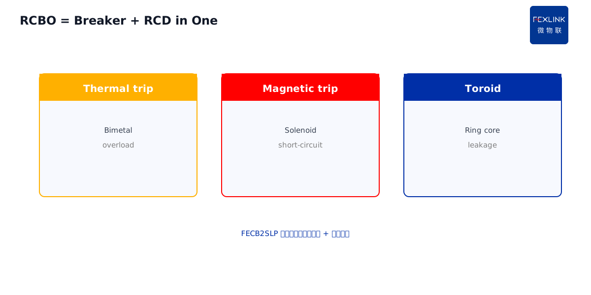
Direct Answer
An RCD (Residual Current Device) works by sensing current imbalance through a zero-sequence toroid. Three phase conductors and the neutral pass through a ring-shaped iron core. Under normal conditions, the vector sum is zero and no flux links the core. When someone touches a live part or equipment insulation fails, a portion of the current returns via earth rather than through the neutral — the vector sum is no longer zero, flux appears in the core, a voltage is induced in the secondary winding, and the tripping mechanism cuts power within 0.1 second.
The threshold is 30 mA. This number is not arbitrary: 30 mA through the human heart for 0.1 second is below the threshold for ventricular fibrillation. Both IEC 61008/61009 and GB/T 13955 enforce this as the personal-protection gold standard. In an office tower, someone touched a metal appliance case and felt a tingle; the RCD tripped. Inspection found a compromised compressor winding. Without the 30 mA fast disconnect, the outcome could have been fatal.
1. The zero-sequence toroid: an unassuming ring
Inside every RCD, the core component is a ring-shaped iron core. All phase conductors (L1/L2/L3) and the neutral (N) pass through the ring — but the protective earth (PE) does not. That is the critical design.
Normal operation: Three-phase currents flow in their respective directions; their vector sum is zero. Whatever current leaves the source returns through the neutral, so flux in the core is zero and the secondary winding has no induced voltage.
Fault operation: Some current leaves the phase conductor through a human body (or an insulation failure point) and returns to the transformer neutral via earth — bypassing the toroid entirely. The vector sum through the ring is no longer zero; it equals the leakage current itself. This imbalance produces flux in the core and induces a voltage in the secondary winding.
Tripping: The induced voltage is either electronically amplified (electronic RCD) or directly drives a solenoid (electromechanical RCD), pushing the trip lever and opening the main contacts within 0.1 second. No external power is needed — the electromechanical RCD is powered by the fault current itself.
2. Why the test button works
The "T" or "Test" button on the RCD faceplate, pressed monthly, deliberately creates an imbalance: it routes a portion of the current around the toroid externally, simulating a leakage fault. The current is typically 75–150 mA (depending on rating) — enough to be detected by the toroid and trigger the trip.
Why press it monthly? To verify the tripping mechanism has not seized and the electronics are still functional. RCDs that sit idle for years can jam mechanically; when a real fault occurs, they fail to trip. This "installed but useless" scenario is common in old buildings. A 2019 plant audit found 11 out of 47 RCDs failed the test button — all were over 8 years old and had never been operated.
3. Two numbers: operating current and time
| Parameter | Meaning | Typical value |
|---|---|---|
| Rated residual operating current IΔn | Must trip at or above this value | 30 mA (personal), 100/300/500 mA (fire/equipment) |
| Break time | From fault to de-energization | ≤0.1 s (AC type instantaneous) |
30 mA is the personal-protection gold standard. GB/T 13955 mandates 30 mA RCDs for wet locations, handheld appliances, and socket circuits. Human body resistance in wet conditions can drop to 1000 Ω; at 220 V that yields ~220 mA through the body — but the RCD cuts at 30 mA, so the body actually sees about 30 mA × 0.1 s = 3 mA·s of charge, well below the ventricular fibrillation threshold.
100 mA and above: Used for fire protection (preventing earth-fault arcing from igniting combustibles). It does not directly protect people but reduces electrical fire risk. A data-center main feeder RCD rated 300 mA operates at this level.
4. RCD vs circuit breaker
People often confuse RCDs with circuit breakers:
- Circuit breaker (MCB/MCCB): Handles overload and short-circuit; trips at 1.13–1.45× rated current to protect wiring.
- RCD: Handles earth leakage; trips on current imbalance to protect people.
- RCBO: Combines both in one device — overload, short-circuit, and leakage protection.
The "leakage protector" switch in a residential distribution box is actually an RCBO: thermal trip (bimetal for overload), magnetic trip (for short-circuit), and zero-sequence toroid (for leakage). The FECB2SLP smart circuit breaker is an RCBO on the next level: beyond traditional protection, it uploads leakage events, waveforms, and timestamps to the cloud; the ESF electrical fire controller then performs residual-current trend analysis.
5. Common nuisance-tripping causes
Frequent RCD trips are not always real leakage:
Line-to-earth capacitive current. Long cables (>100 m) have distributed line-to-earth capacitance that generates tens of milliamps of capacitive leakage at AC voltage — right at the 30 mA threshold. Switching to a 100 mA AC-type RCD resolves this.
VFD / switch-mode power supply interference. VFD outputs are high-frequency PWM waveforms containing DC components. AC-type RCDs cannot detect this "pulsating DC" residual current — which is why VFD-equipped workshops require F-type or B-type RCDs (see KD-0059 and KD-0060).
Simultaneous equipment startup. Large-motor starting transients produce earth-referenced spikes that RCDs misread as leakage.
PE and N wiring errors. When three-phase loads are unbalanced, miswired N conductors create false imbalance through the toroid.
6. Smart RCD upgrade
Traditional RCDs tell you something happened only when they trip. Smart RCDs add:
Continuous residual-current monitoring. The ESF electrical fire controller continuously records residual current even when not tripped. A rising trend (10 mA climbing toward 25 mA) triggers early warning before reaching the 30 mA trip point.
Leakage waveform upload. On a real trip, the waveform for the 10 seconds before tripping is stored. Slow climb = insulation aging; sharp spike = personnel shock. The waveform tells them apart.
Leakage circuit localization. A distribution box with 10 circuits — when the main RCD trips, which circuit leaked? Per-circuit residual current monitoring directly identifies the culprit. The FECB2SLP smart breaker provides exactly this — per-pole monitoring with event upload.
Scope and Limitations
This article references current IEC 61008/61009 and GB/T 13955 standards. The 30 mA personal-protection threshold applies to AC 220 V/380 V systems; DC systems and special locations follow their own codes. RCDs cannot replace overcurrent protection and must coordinate with circuit breakers. Monthly test-button operation is mandatory; RCDs that are never tested are unreliable. Office towers, factories, and data centers mentioned are anonymized.