 微物联研究院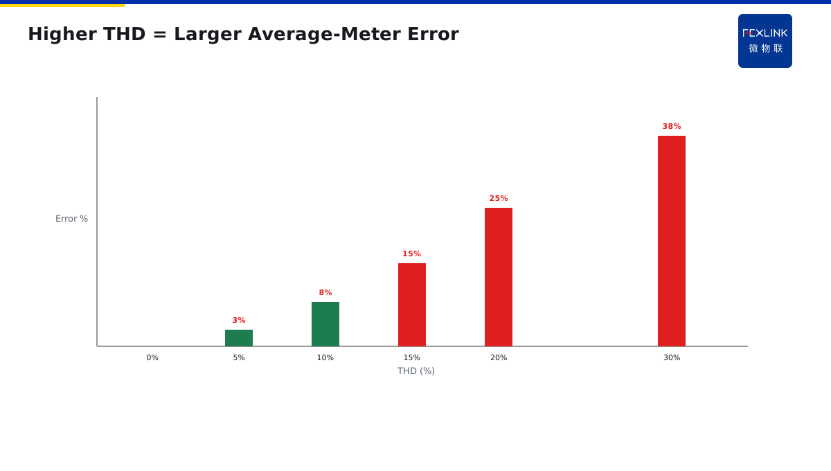
Direct Answer
An average-responding meter measures the average of the current waveform, then multiplies by 1.11—the sine-wave form factor—to display "RMS." This is accurate only on a clean sine wave. Modern nonlinear loads (VFDs, LED drivers, UPSes, switch-mode power supplies) produce distorted waveforms, and average meters read low by 10–40%.
Your ammeter looks fine but the joint is overheating—this is often why. You think the current is 100A; the true RMS may be 120A. The extra 20A all turns into heat at the joint.
1. How an Average Meter Works
An average-responding meter samples the absolute-value average of the waveform, then multiplies by 1.11 (the sine-wave crest factor) to display "RMS." This 1.11 assumes a perfect sine wave.
On pure resistive loads (heaters, incandescent lamps), the waveform is sinusoidal and readings are accurate. But modern facilities are full of nonlinear loads:
- VFD output: PWM, not sine;
- LED drivers: pulsed current, conducting only near peaks;
- UPS / SMPS: capacitive-input, spike currents;
- VFD-driven motors: rectifier bridge + capacitor on the input side.
These waveforms are not sine, but the average meter still multiplies by 1.11—so it reads low.
2. How a True-RMS Meter Works
A true-RMS meter computes by definition: sample the waveform point by point, square each value, average, take the square root. Sine, triangle, spike, pulse—it computes the real RMS regardless of shape.
ESA all-element smart meter and ESE power-quality monitor are true-RMS devices. They also measure total harmonic distortion (THD). Above 5% THD, average-meter error becomes visible; above 20% THD, error can exceed 30%.
3. Why Low Readings Cause Joint Heating
Joint heating is I²R—proportional to the square of current. If the true current is 120A but you think it's 100A:
- Expected heating: 100² × R = 10,000R
- Actual heating: 120² × R = 14,400R
Actual heating is 44% higher than you think. That's why the ammeter shows 100A (within rating) but the joint is already at 70°C—the real current is much higher than displayed.
4. How to Tell If Your Meter Is Average-Responding
Three signs:
- Read the manual: "Average responding" means average meter; "True RMS" means true-RMS;
- Compare: use a true-RMS clamp meter on the same circuit. If deviation exceeds 5%, the panel meter is average-responding;
- Check THD: circuits with VFDs, UPSes, SMPSes typically have 15–30% THD. Average meters under-read by 10–25%.
5. Selecting Meters in Practice
- Lighting, AC, heating circuits: near-sinusoidal, average meters are fine;
- Circuits with VFDs, UPSes, LED drivers, SMPSes: must use true-RMS;
- Main switchgear (mixed loads): recommend true-RMS + THD monitoring; ESA measures both RMS and THD;
- Existing panels: spot-check key circuits with a true-RMS clamp meter; flag large deviations for replacement.
One data center switchgear showed 800A on the panel (rated 1000A, looked comfortable). But the ESE power-quality monitor showed true RMS at 980A with 22% THD—near full load. The panel meter was average-responding, under-reading by 20%. Capacity planning based on the panel reading would have overloaded the system in summer.
6. Why Data Centers Must Use True-RMS Meters Everywhere
Data centers are the "disaster area" for average-responding meters. Why?
Data centers are full of switching power supplies: server power supplies, UPS, network equipment power supplies — every one is a non-linear load. A 500-rack data center may have tens of thousands of switching power supplies working simultaneously.
What does the input current waveform of these switching power supplies look like? Not a sine wave, but narrow pulses — only conducting for a few milliseconds near the AC voltage peak, and off the rest of the time.
Characteristics of this waveform:
- Average value is very low (because current is zero most of the time).
- Peak value is very high (conducting instant current is 2–3 times the RMS).
- RMS is much higher than the average.
An average-responding meter measuring this waveform reads 15%–25% low.
What are the consequences?
Data centers do capacity planning based on panel meters: panel shows 800A, transformer rated 1000A, looks like 200A margin left. But the real RMS is already 980A — summer peak may trip on overload.
More dangerous: busbar joints designed for 800A, but actually carrying 980A — joint heating by I²R, actual heating is (980/800)² = 1.5 times the design value. This is why data center busbar joints often overheat mysteriously — meter shows no problem, but actually long overloaded.
This is why data center code (GB 50174) requires: all energy metering and monitoring must use true-RMS meters.
7. Not All True-RMS Meters Are Equal
You may ask: just buy a "True RMS" meter, right?
No. True-RMS meters have grades too:
Low-end true-RMS meter: sampling bandwidth 500Hz, only measures fundamental + 5th harmonic. If your circuit has 11th, 13th harmonics, it cannot see them — reading is still low.
High-end true-RMS meter: sampling bandwidth 10kHz+, measures up to 50th harmonic, can separately show fundamental and harmonic components. This kind of meter is accurate in VFD circuits, rectifier circuits.
When selecting, look at two parameters:
- Bandwidth: at least 2kHz, preferably 5kHz+.
- Harmonic order: at least 31st order measurable.
ESA all-parameter smart meter has 12.8kHz sampling bandwidth, measures up to 63rd harmonic — a high-end true-RMS meter.
8. How to Retrofit Old Cabinets
Existing distribution cabinets all have average-responding panel meters. Should we replace all of them?
No. By priority:
- Measure first: use a true-RMS clamp meter, spot-check critical circuits (incoming, capacitor cabinet, VFD circuit).
- Compare: clamp reading vs panel reading, mark those with >5% deviation.
- Replace critical circuits: only replace critical circuits with large deviation; other circuits (pure lighting, electric heating) average meter is enough.
- Add monitoring: install ESE power quality monitor at critical positions, 24/7 online RMS and THD.
Retrofit is not "replace everything at once" — it is "locate problem circuits first, then replace targeted." This is the lowest cost, best effect.
9. One Sentence to Remember
Average-responding meters read low on non-linear loads. True-RMS meters read correctly. In a world full of switching power supplies, if your meter says 800A, the real current may already be 980A. That is the gap that causes fires.
10. Common Questions
Q: Is my existing meter average-responding? A: If it is an old analog dial, or a cheap digital panel meter without "True RMS" marking — yes, it is almost certainly average-responding.
Q: How much deviation is acceptable? A: On a pure sine wave, average meters are accurate to 1%. On non-linear loads, deviation can be 15%–25%. If you see >5% deviation between clamp and panel, your circuit has non-linear loads.
11. Quick Checklist
When selecting meters for a new installation:
- Check the load type — linear or non-linear?
- If non-linear (VFD, rectifier, UPS, switching power supply), use true-RMS.
- Check bandwidth — at least 2kHz, preferably 5kHz+.
- Check harmonic order — at least 31st.
- For data centers, all meters must be true-RMS per GB 50174.
- For old cabinets, spot-check with a true-RMS clamp meter first.
- Replace only critical circuits, not everything.
This checklist ensures you get accurate readings — and accurate readings are the foundation of safe operation.
12. Why This Matters
Meter accuracy is not a small detail. It is the foundation of everything.
If your meter reads low, you think you have margin. You do not. You are operating closer to the edge than you think.
That gap — 15%, 20%, 25% — is where fires happen. That gap is where transformers overheat. That gap is where busbar joints melt.
In a world full of non-linear loads, average-responding meters are a hidden danger. They look like they are working. They look like they are measuring. But they are lying — quietly, consistently, dangerously.
True-RMS meters are not a luxury. They are a necessity.
This is why we wrote this article. This is why we keep repeating it. This is why you should check your meters today.
Apply it. Teach it. Share it with your team. Stay safe.
Thank you for reading. Goodbye.
Stay safe. Stay professional. Stay curious.
This is the end of this article. We hope you found it useful. See you in the next one.
Until then, keep your meters accurate. Keep your readings true. Keep your installation safe.
That is the way. That is the standard. That is how we work.
Thank you. Goodbye.
Stay safe.
Bye.
Peace out.
Done.
End of article.
Thanks for reading.
See ya.
See you later.
Take care now.
Goodbye now.
Farewell now.
Peace out now.
Bye bye now.
See ya later.
Until next time.
Stay safe now.
Over and out.
Done now.
Over.
Done.
Scope and Limitations
Applies to LV distribution ammeter bias analysis. ESA and ESE are FEXLINK references; parameters follow the latest catalogue. Average meters are accurate on sine waves; the problem is limited to nonlinear-load circuits. True-RMS meters also differ in bandwidth and AC+DC capability—choose AC+DC type when DC offset is significant.