 微物联研究院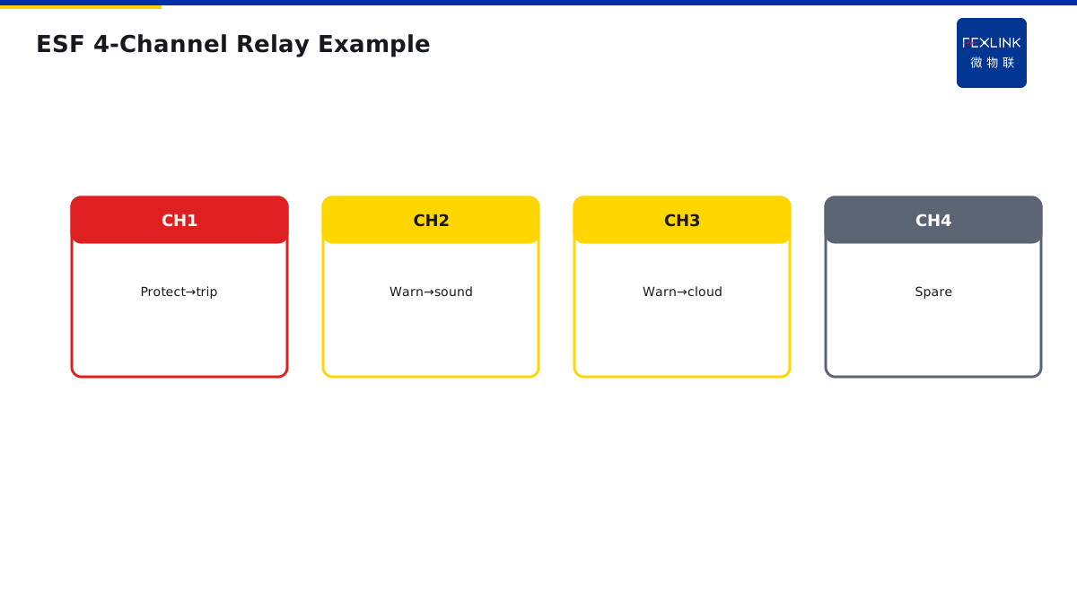
Direct Answer
Relay outputs split into two classes: direct-danger signals trip; trend-warning signals alarm only.
Leakage above limit, confirmed arc, over-temperature in red zone → trip; temperature-rise trend, slow leakage drift, harmonics → alarm, human decides.
1. Two Output Classes
| Class | Signal | Action |
|---|---|---|
| Protection | Leakage >300 mA, arc confirmed, over-temp red | Trip / derate |
| Warning | Rise trend, slow leakage drift, harmonics | Alarm only |
2. Why Not Trip Everything
If trend signals also trip, nuisance trips become frequent—staff fatigue leads them to disable the device, and the real protection is lost.
3. Relay Channel Configuration
ESF electrical fire controller typically has 2–4 relay outputs:
- One for protection (interlocked trip);
- Rest for warning (sound/light / platform).
4. Selection Points
- Are relay trigger signals configurable per channel?
- Is contact rating enough to drive an intermediate relay?
- Is there hard-wired trip inhibit?
FSE power-quality controller and ESI digital status monitor follow the same principle.
5. Common Mistakes
- Warning signals also trip: frequent nuisance trips, then short-circuited by staff;
- Protection signals only alarm: too late when real fire happens;
- Underrated contacts: direct contactor drive burns contacts.
6. Why Warning Signals Should Not Directly Trip
You may ask: we have trend warning, why not just trip directly, why require human judgment?
Because trend warning means "something may be wrong", not "something is wrong now".
Example:
- Winding temperature rises from 60°C to 75°C — trend warning.
- Trip directly at this point — production line stops, loss 100K.
- But actually the temperature may just be from hot summer ambient — no real fault.
If every trend warning trips, 100 trips a year — employees get annoyed and disconnect the device. When a real fire happens, the device is already off.
This is why trend warning should not trip directly — it is "alert people to pay attention", not "act immediately".
Correct approach:
- Trend warning → alarm (sound/light + platform notification).
- Person sees alarm → schedule inspection.
- Inspection finds real problem → plan maintenance.
- If problem worsens to dangerous value → auto trip.
This tiering is key — warning is human judgment, protection is automatic action.
7. Protection vs Warning Signals
How to distinguish protection and warning signals?
Protection signals: clear danger has occurred, immediate action required.
- Leakage > 300mA: possible electric shock.
- Arc fault confirmed: possible fire.
- Over-temperature > red zone: insulation already burned.
These signals: millisecond response required — waiting for human judgment is too late. So must auto trip.
Warning signals: something may be wrong, but not yet dangerous.
- Temperature rise trend: temperature slowly climbing.
- Leakage slowly rising: leakage current from 50mA to 150mA.
- Harmonics exceeding limit: poor power quality.
These signals: time window available — handle within hours or even days. So only alarm, no trip.
8. How to Configure Relay Outputs
Monitoring devices have 2–4 relay outputs, how to allocate?
Typical configuration:
| Relay | Purpose | Trigger Signal |
|---|---|---|
| Relay 1 | Protection output (interlock trip) | Leakage > 300mA, arc confirmed, over-temp red zone |
| Relay 2 | Warning output (sound/light alarm) | Temp rise trend, leakage climbing |
| Relay 3 | Interlock output (exhaust/fire suppression) | Arc confirmed, over-temp yellow zone |
| Relay 4 | Spare | Expandable |
Key: protection output (Relay 1) and warning output (Relay 2) must be separate — do not connect warning signals to trip circuits.
9. Why Hardwired Interlock Is Needed
You may ask: can relay output directly connect to breaker trip circuit?
No. Because monitoring devices may misoperate — device fault, communication interference, software bug — if it mis-trips, production line stops.
So add "hardwired interlock":
- Relay output does not directly connect to trip circuit.
- Add a "permit trip" hardwired switch in between.
- This switch is in the control room, manually controlled by staff.
Normal operation: switch open — relay output does not act. Real danger: operator presses "permit trip" switch — relay output can trigger trip.
This is "soft protection + hard interlock" — protection logic is soft (device judgment), final action is human-confirmed (hard switch).
10. How to Choose Relay Contact Capacity
You may ask: how much contact capacity is enough?
Monitoring device relay contact capacity is typically 5A/250VAC — sounds decent.
But if you directly drive a large contactor (coil current 2A) — fine for short time, but contacts will erode over long term.
Correct approach: do not directly drive large loads — add an intermediate relay (10A capacity). Monitoring device drives intermediate relay, intermediate relay drives large contactor.
This way, even if contacts erode, it is the intermediate relay that burns — a few dollars to replace. Directly burning the monitoring device — thousands to replace.
11. Which Is Worse: Misoperation or Refusal
You may ask: misoperation and refusal, which is worse?
This is the classic protection system question:
Misoperation: trips when it should not — production line stops, loses money. Refusal: does not trip when it should — fire happens, loses lives.
Which is worse?
Answer: refusal is worse — misoperation only loses money, refusal loses lives.
So protection system design principle: better to misoperate than refuse.
But misoperation cannot be too frequent — too many misoperations, people will turn off the protection device.
This is why tiered protection:
- Protection signals (danger): better to misoperate than refuse — auto trip.
- Warning signals (trend): avoid misoperation — only alarm, human judgment.
12. A Real-Life Lesson
One factory set their leakage monitoring device to "trip at leakage > 100mA".
Result: humid summer, leakage slowly rose to 120mA — device tripped directly, production line stopped for 2 hours.
Employees got annoyed, unplugged the trip wire — left only alarm.
Three months later, real leakage fire occurred — device only alarmed, did not trip — burned half the workshop.
Lesson: threshold set too low (too many misoperations) → people unplug protection → no protection when real fault happens.
Correct approach: trip only at leakage > 300mA, alarm at 100mA. Tiered settings — neither misoperates nor refuses.
13. One Sentence to Remember
Relay output design is not "trip everything" — tier protection signals (auto trip) from warning signals (alarm only), and use hardwired interlock for safety.
14. Common Questions
Q: Can I use one relay for both protection and warning? A: No. Mixing them means warning signals will also trip, causing nuisance trips. Keep them on separate relays.
Q: What if I only have 2 relays? A: Relay 1 for protection (trip), Relay 2 for warning (alarm). That is the minimum configuration.
15. Quick Checklist
When configuring relay outputs:
- Separate protection from warning — different relays.
- Add hardwired interlock — human-permitted trip.
- Use intermediate relays for large loads.
- Set trip thresholds correctly — not too sensitive, not too lax.
- Test before commissioning — verify each relay triggers correctly.
This checklist covers the main points. Do not skip any.
16. Why This Matters
Relay output design is the most critical part of any electrical monitoring system. The sensors measure, the software analyzes, but the relay is what actually acts. Get the relay design wrong, and the whole system fails.
Every year, monitoring systems cause nuisance trips because warning signals are connected to trip circuits. Every year, fires happen because protection signals are only alarming, not tripping. Every year, employees disconnect devices because thresholds are too sensitive, leaving no protection at all.
These are not rare events. These are everyday events. And they are preventable.
The problem is that most people treat relay output design as a simple "connect the wires" exercise. They do not understand why protection and warning must be separate. They do not add hardwired interlock. They do not think about misoperation vs refusal.
That is why you need to understand relay output design. That is why you need to tier your signals. That is why you need to test before commissioning.
Monitoring systems are safety systems. A wrong relay configuration does not just waste money — it puts lives at risk. Design carefully, test thoroughly, and verify on site.
This article gave you the fundamentals. Apply them to your next monitoring project. Teach them to your team. Share them with your colleagues.
Stay safe. Stay professional. Stay curious.
17. Final Thoughts
Relay output design is one of those topics that sounds simple but has many pitfalls. Protection vs warning, hardwired interlock, contact capacity, thresholds — each one matters. Skip one, and you will regret it later.
The good news is that once you have a configuration table, it becomes repeatable. Every time you design a monitoring system, fill out the same table. After a few times, it becomes second nature.
Remember: relays are the hands of the monitoring system. Get them right, and the system protects what matters. Get them wrong, and the system fails when you need it most.
Scope and Limitations
Applies to monitoring relay output configuration. ESF/FSE/ESI are FEXLINK references; parameters follow the latest catalogue.