 微物联研究院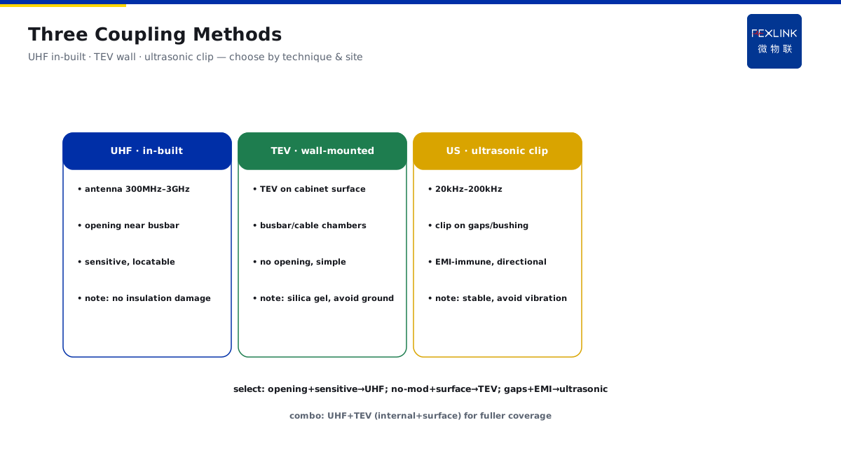
Direct Answer
PD (partial discharge) sensors have arrived, but the construction crew is unsure how to install them so the measurement is accurate. The answer: three installation steps — choose the coupling method by the detection technique (UHF in-built / TEV on the cabinet wall / ultrasonic clip-on); place measurement points near high-discharge areas such as the busbar chamber and cable chamber; measure the background noise once before commissioning as the baseline; after installation, perform a no-load verification to confirm the sensor signal path is normal before putting it into service.
At one industrial park's 10kV switchgear PD monitoring: TEV sensors were attached to the cabinet wall (busbar and cable chamber areas), UHF was in-built near the busbar, ultrasonic sensors were clip-mounted on cabinet gaps; background noise was measured before commissioning (TEV baseline 12dBmV); a no-load verification confirmed each signal path. Three months after commissioning, cable-chamber TEV rose from 12dBmV to 28dBmV (alarm); a power-off inspection confirmed cable-termination discharge — the signal was trustworthy. Installation core: coupling method, measurement-point location, and baseline verification — install it right, and the measurement is accurate.
Because:
- The coupling method determines "whether it can receive": UHF in-built / TEV wall-mounted / ultrasonic clip-on each has its applicable scope;
- The measurement-point location determines "what it receives": busbar and cable chambers are high-discharge areas;
- The background-noise baseline determines the "judgment reference": measure once before commissioning so later changes have a benchmark;
- The no-load verification determines "whether the signal is trustworthy": only put it into service after the signal path is confirmed.
Key insight: "install in the right place, measure the right baseline, verify the right path" — the three essentials of reliable PD monitoring. Location + baseline + verification — trustworthy data starts with standardized installation.
At one plant, TEV sensors were mounted at the cabinet bottom (far from the cable chamber): after commissioning the signal was weak with heavy interference, and the data was untrustworthy. Rectification: moved to the busbar/cable-chamber area, re-measured the background-noise baseline, and passed no-load verification. Lesson: a wrong location means inaccurate measurement — place points near high-discharge areas and measure the baseline before commissioning.
1. Coupling Methods of Each Sensor
Step one: how to choose the coupling method.
UHF in-built:
- Principle: built-in antenna receives high-frequency electromagnetic waves (300MHz–3GHz);
- Applicable: internal discharge detection in switchgear/transformers;
- Installation: cabinet opening or dedicated interface, near the busbar;
- Characteristics: high sensitivity, good location capability;
- Note: confirm the opening with the cabinet manufacturer (do not damage insulation).
TEV wall-mounted:
- Principle: transient earth voltage (propagates along the cabinet surface);
- Applicable: external detection on switchgear (no opening);
- Installation: attached to the cabinet wall (busbar/cable-chamber areas);
- Characteristics: simple installation, no cabinet modification;
- Note: firm adhesion (silica gel/double-sided tape), avoid grounding interference.
Ultrasonic clip-on:
- Principle: receives ultrasonic signals (20kHz–200kHz);
- Applicable: cabinet gaps/insulators/bushing through-walls;
- Installation: clipped on cabinet gaps or sensor seats;
- Characteristics: EMI-immune, directional;
- Note: firm clipping, avoid vibration interference.
Selection comparison:
- Opening allowed + highest sensitivity: UHF in-built;
- No cabinet modification + surface detection: TEV wall-mounted;
- Local gaps + EMI immunity: ultrasonic clip-on;
- Multi-method combination: UHF + TEV (covering internal + surface).
Key insight: choose the coupling method by detection technique and on-site conditions. UHF when opening is allowed, TEV when not modifying the cabinet, ultrasonic for local gaps — combinations give broader coverage.
2. Measurement-Point Location
Step two: where to install.
High-discharge areas:
- Busbar chamber: busbar joints (thermal expansion/loosening discharge);
- Cable chamber: cable terminations/joints (weak insulation points);
- Breaker chamber: contacts/arc chamber (operation wear);
- Bushing through-walls: bushing roots (concentrated electric field).
Layout principles:
- Busbar chamber: at least 1 point per busbar section;
- Cable chamber: 1 point per outgoing bay (near cable terminations);
- Breaker: near contacts (optional, frequent-operation locations);
- Space-limited: prioritize busbar + cable chambers (highest discharge areas).
Notes:
- Avoid grounded metal (shields the signal);
- Avoid strong EMI sources (be cautious with ultrasonic near large-current busbars);
- Keep the cabinet surface clean (firm adhesion);
- Record point numbers and locations (installation records).
Example:
- 10kV incoming cabinet: busbar TEV + UHF, cable-chamber TEV;
- Feeder cabinet: cable-chamber TEV (per bay);
- Transformer cabinet: body ultrasonic + oil temperature (combined).
Key insight: place points in high-discharge areas. Busbar + cable chambers first, avoiding interference sources — a right location gives the signal value.
3. Background-Noise Baseline Measurement
Step three: how to measure the baseline.
Why measure a baseline:
- On-site noise (corona/interference/environment) affects interpretation;
- Without a baseline you cannot distinguish discharge signals from background noise;
- The baseline is the zero point for later trend judgment.
Measurement method:
- Measure once before commissioning (when no discharge interference);
- Record each point separately (noise differs per point);
- Record continuously (take the mean of short-term fluctuation);
- Record operating conditions (load/weather/neighbor equipment states).
Baseline content:
- TEV amplitude (dBmV) and pulse count;
- UHF signal strength (dBm) and event count;
- Ultrasonic amplitude (dB) and event count;
- Per-point reference-value table (archived).
Notes:
- Note areas with high environmental noise (reference for later interpretation);
- Re-measure the baseline periodically after commissioning (season/condition changes);
- For abnormal baseline (sudden rise), investigate the interference source first.
Key insight: the baseline is the zero point of judgment. Measure before commissioning, record point by point, archive with notes — later changes have a reference.
4. No-Load Signal Verification
Step four: how to confirm the installation is correct.
Verification purpose:
- Confirm the sensor signal path is normal;
- Exclude installation errors (poor contact/wrong wiring);
- Verify data is uploaded to the platform correctly.
Verification method:
- Measure each point at no-load/low load;
- Compare with the baseline (should be close to baseline values);
- Check data upload (visible on the platform);
- Troubleshoot installation on abnormal signals (no signal/sudden change).
Common-problem troubleshooting:
- No signal: wiring/sensor fault/location shielding;
- Weak signal: loose adhesion/wrong location;
- Sudden signal change: interference/loose contact;
- Data not uploading: communication/configuration issue.
Pass criteria:
- Each point uploads normally;
- Amplitude close to baseline (no obvious anomaly);
- Interference sources identified and recorded;
- Installation records and labels complete.
Key insight: no-load verification is the installation acceptance. Path normal, data uploaded, baseline compared — only then put it into service.
5. Installation Records and Labels
Step five: how to leave a standardized trail.
Record content:
- Point number and location description;
- Sensor model and coupling method;
- Background-noise baseline value;
- Installation date and crew;
- Verification result and notes.
Label requirements:
- Paste point labels on the cabinet (number + type);
- Corresponding system-point configuration (platform sync);
- Archive records (engineering documents + maintenance ledger).
Follow-up management:
- Baseline re-measurement cycle (quarterly/semi-annual or on condition changes);
- Abnormal-signal records (compared with installation records);
- Update records on retrofit/point moves;
- Sensor-life management (replacement cycle).
Key insight: records and labels are the guarantee of traceability. Number + baseline + verification — complete data, evidence-based operation and interpretation.
6. Product Landing: Digital Electrical Intelligent Supervision System
FEXLINK products land PD installation:
- Multi-sensor access: unified access for UHF/TEV/ultrasonic;
- Point management: online management of numbers/locations/baselines;
- Trend interpretation: PD trends referenced to baselines;
- Verification tooling: commissioning checks and data validation.
Design principle in one sentence: "install right, measure accurately, verify passed." Coupling method + points + baseline + verification — trustworthy PD data.
Pre/post-installation checklists:
- Before: confirm cabinet structure and opening plan (UHF); prepare silica gel/double-sided tape (TEV); confirm clip locations (ultrasonic);
- During: place points per "busbar + cable chambers first"; firm adhesion (silica gel/stable clipping); avoid grounded metal and strong EMI sources;
- After: measure the background-noise baseline point by point (record conditions); no-load verify signal paths (compare baseline); confirm data upload to the platform; paste point labels and archive records.
7. Common Installation Misconceptions
- Random placement: sensors at the cabinet bottom. Consequence: weak signal/heavy interference. Correct: near busbar/cable-chamber high-discharge areas.
- No baseline: reading signals immediately after commissioning. Consequence: cannot distinguish discharge from noise. Correct: measure background noise before commissioning as the baseline.
- No no-load verification: leaving right after installation. Consequence: poor contact/wrong wiring unknown. Correct: verify the signal path at no load.
- Loose adhesion: TEV sensors loosely attached. Consequence: signal attenuation/instability. Correct: silica gel + firm adhesion.
- No records or labels: not registered after installation. Consequence: no reference for later interpretation/points hard to find. Correct: archive number + baseline + verification records.
Scope and Limitations
This article provides an on-site installation guide for switchgear PD sensors (coupling methods, measurement-point locations, background-noise baselines, no-load verification, installation records) for PD monitoring on 10kV and above switchgear. Specific installation plans must be determined by cabinet structure, on-site space, and manufacturer requirements; cabinet openings must be confirmed with the cabinet manufacturer (do not damage insulation); installation and verification must be performed by qualified personnel per procedures. All cases are anonymized (a certain industrial park/a certain plant) and do not refer to any specific customer.