 微物联研究院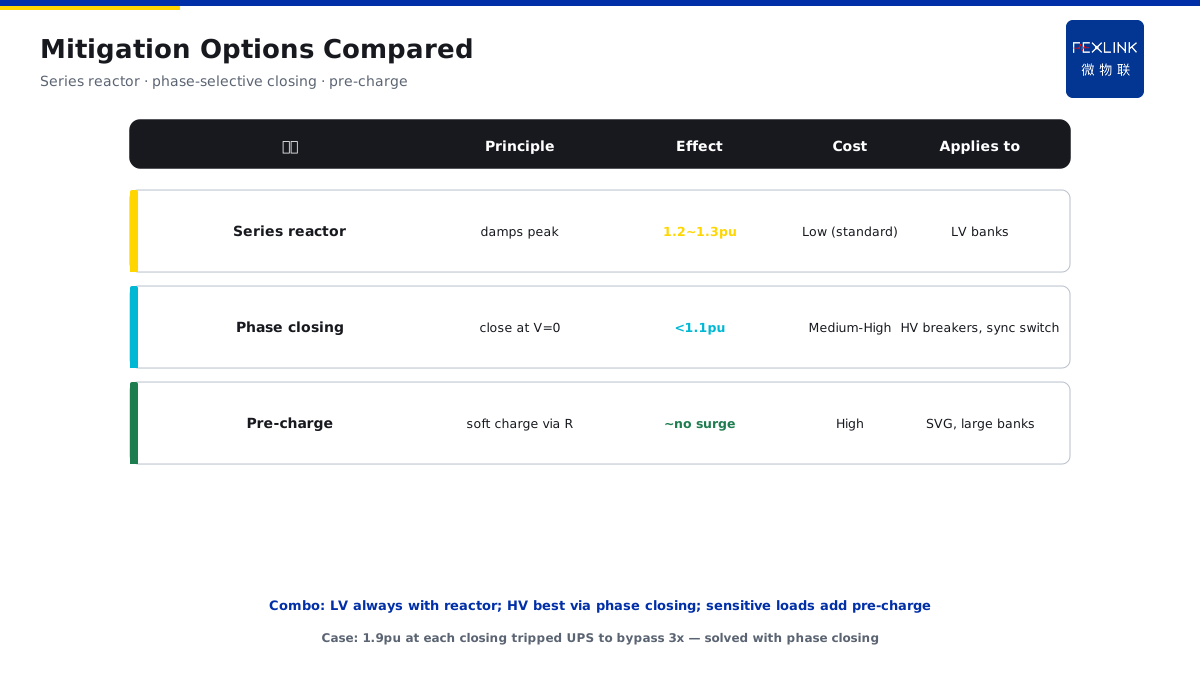
Direct Answer
When the reactive power compensation bank switches capacitors, the VFD alarms — not because the VFD is broken, but because the switching creates transient overvoltage.
Many factories have this problem: every time the compensation bank switches a capacitor, the nearby VFD alarms or resets. They check the VFD, it is fine. They check the grid, it is fine. Only at the moment of switching does the problem happen.
Why? Because:
- Capacitor switching: capacitor and system inductor form an oscillation circuit, creating high-frequency transient overvoltage;
- Vacuum switch: current chopping and reignition create steep-front overvoltage;
- Shock conduction: overvoltage travels through power lines to the VFD, which cannot handle it and alarms.
Key insight: capacitor switching is not just "close the switch and done" — it instantly creates high-frequency oscillation. The amplitude and frequency depend on system parameters. Without suppression, nearby sensitive equipment has problems.
One factory, every time the compensation bank switched, the nearby PLC reset. They investigated for a week, finally found it was capacitor-switching transient overvoltage. Installed surge arresters, problem solved. Without understanding this mechanism, they might have replaced several PLCs and still not found the cause.
1. Capacitor Switching Oscillation Circuit
Why does capacitor switching create overvoltage? Because capacitor and system inductor form an oscillation circuit.
Equivalent circuit:
- System inductance L (transformer leakage + line inductance);
- Capacitance C (compensation capacitor);
- At the moment of closing, L and C form LC oscillation.
Oscillation frequency:
- f = 1 / (2π√(LC));
- Usually hundreds to thousands Hz;
- Much higher than power frequency, it is transient.
Overvoltage amplitude:
- Depends on system impedance and capacitor size;
- Usually 2~3 times rated voltage;
- Can be higher in severe cases.
Key: capacitor switching = LC oscillation circuit closing = high-frequency transient overvoltage. This is physics, cannot be avoided, only suppressed.
2. What Determines Overvoltage Amplitude and Frequency
What determines overvoltage amplitude and frequency?
System impedance
- Higher system impedance (smaller transformer, longer lines) = higher overvoltage;
- Lower system impedance (bigger transformer, shorter lines) = lower overvoltage.
Capacitor size
- Bigger capacitor = lower oscillation frequency, possibly higher amplitude;
- Smaller capacitor = higher oscillation frequency, possibly lower amplitude.
Closing phase
- Closing at voltage peak = worst overvoltage;
- Closing at voltage zero = lightest overvoltage.
Key: overvoltage is not fixed, depends on system parameters. Same capacitor, different systems, different overvoltage amplitude and frequency.
3. Vacuum Switch Current Chopping and Reignition
Besides capacitor switching oscillation, the vacuum switch itself also creates overvoltage.
Current chopping
- Vacuum switch cuts current before zero crossing;
- Current is suddenly chopped, energy in inductor has nowhere to go;
- Creates high overvoltage.
Reignition
- After switch opens, contacts break down again;
- Arc forms again, then breaks again;
- Repeats several times, each time creates overvoltage.
Why is vacuum switch especially prone?
- Vacuum has strong arc extinguishing, current is easily chopped;
- Chopping current value is higher than air switches;
- More likely to create chopping overvoltage.
Key: vacuum switch itself is an overvoltage source. Using vacuum switch to switch capacitors makes overvoltage worse.
4. Steep-Front Overvoltage Cumulative Damage
Why is steep-front overvoltage so damaging to insulation?
Because:
- Very short rise time (nanoseconds);
- Very high frequency (MHz range);
- Uneven electric field distribution inside insulation;
- Repeated shocks, cumulative damage.
Damage to motor insulation:
- Motor winding turn insulation is especially sensitive to steep-front;
- One or two shocks may be fine;
- Hundreds or thousands of shocks, insulation slowly ages, eventually breaks down.
Key: steep-front overvoltage does not break things at once, it is cumulative damage. Every switching shocks it a bit, over time it fails.
5. Three Engineering Suppression Methods
How to suppress capacitor-switching transient overvoltage? Three methods:
Type 1: Zinc Oxide Arrester (SPD)
- Parallel across capacitor;
- When overvoltage comes, arrester conducts, clamps voltage;
- Simplest, most commonly used.
Type 2: Series Reactor
- Small reactor in series with capacitor;
- Changes LC oscillation frequency, avoids resonance;
- Also suppresses closing inrush current.
Type 3: Zero-Crossing Switch
- Closes at voltage zero crossing;
- Reduces overvoltage at the source;
- More expensive than regular switch, but best effect.
FEXLINK FS surge protective device monitor monitors zinc oxide arrester status — detects aging before arrester fails.
6. A Real Case
One factory, every time the compensation bank switched:
- Nearby VFD would alarm;
- Checked VFD, no problem;
- Checked grid, no problem;
- Finally used oscilloscope, found 3x rated voltage high-frequency oscillation at switching;
- Installed zinc oxide arresters, problem solved.
Without understanding capacitor-switching transient overvoltage, they might have replaced several VFDs and still not found the cause.
7. Three Common On-Site Mistakes
Mistake 1: think the VFD is low quality. Not the VFD's fault, it is switching overvoltage shock. Suppress the overvoltage, do not replace the VFD.
Mistake 2: install arresters but do not monitor them. Arresters age, using an aged arrester is like having none. Monitor arrester status.
Mistake 3: ignore steep-front cumulative damage. One shock is fine, does not mean always fine. Repeated shocks cumulatively damage insulation.
8. One Sentence to Remember
Capacitor switching = LC oscillation = transient overvoltage. Vacuum switch chopping/reignition = steep-front overvoltage. Three suppression methods: arrester + series reactor + zero-crossing switch.
Do not replace the VFD when it alarms, first check if it is switching overvoltage.
9. Common Questions
Q: How many times rated voltage is typical capacitor switching overvoltage? A: Usually 2~3 times rated voltage, can be higher in severe cases. Depends on system impedance, capacitor size, closing phase.
Q: Do all capacitor banks create overvoltage? A: Yes, just severity differs. High system impedance, big capacitor, bad closing phase = severe. Low impedance, small capacitor, zero-crossing switch = light.
10. Why This Is Becoming More Important
As factories add more sensitive equipment — VFDs, PLCs, smart instruments — the impact of transient overvoltage becomes more visible. A generation ago, nobody noticed these problems. Now they cause alarms, resets, and premature equipment failure.
That is why power quality monitoring is not just about harmonics and unbalance. It is about transients. FEXLINK ESE power quality monitor captures switching transients, helps you find the root cause, not just the symptom.
Stay safe. Stay professional. Stay curious.
11. Quick Checklist
Before you blame the next VFD failure on low quality, run through this checklist:
- Does the problem happen only when the capacitor bank switches?
- Have you measured what the voltage looks like at the moment of switching?
- Do you have surge arresters installed, and are they still healthy?
- Do you have series reactors or zero-crossing switches?
- Have you considered cumulative damage to motor insulation from repeated shocks?
If you answered "no" to most of these, your VFD problems may not be VFD problems at all. They may be power quality problems caused by capacitor switching. Fix the root cause, not the symptom.
The FEXLINK platform helps you find this. ESE power quality monitor captures transients. FS SPD monitor tracks arrester health. Together, they show you what is really happening at switching moments, not just what the steady state looks like.
12. How to Build a Routine
A good power quality routine starts with baseline. Measure voltage, current, harmonics, and transients on a normal day. Record what typical switching looks like. Then track how these parameters change over months.
When transient overvoltage amplitude starts increasing, you know arresters are aging. When VFD alarms start clustering around switching moments, you know suppression is not enough. You schedule an inspection. You compare to historical data. You decide whether to upgrade the switchgear or add more suppression.
This is condition-based power quality management. It saves money, reduces downtime, and avoids the panic of "VFD failed unexpectedly, production stopped."
Start today. Identify your oldest capacitor bank. Install transient monitoring. Build your baseline. Then you can make smart upgrade decisions, not expensive emergency replacements.
Final Thoughts
Transient overvoltage is the hidden stress on modern electrical systems. Old equipment could tolerate it. New sensitive equipment cannot. Every capacitor switch is a small shock. Over years, those shocks add up.
But it does not have to be that way. With good monitoring and suppression, you can control these transients. You can protect your sensitive equipment. You can avoid unnecessary VFD replacements.
Do it smart. Do it early. Do it with data.
Your VFDs will thank you. Your production team will thank you. Your budget will thank you. Stay safe, and keep monitoring.
See you in the next article. Take care, and remember: transient overvoltage tells a story — read it early, read it right.
That is all for this article. If you have questions about your own capacitor bank and VFD problems, you know where to look first. Good luck, and stay power-quality-safe. Until next time. Keep your grid clean, keep your transients controlled, and keep your equipment running reliably year after year. Thank you.