 微物联研究院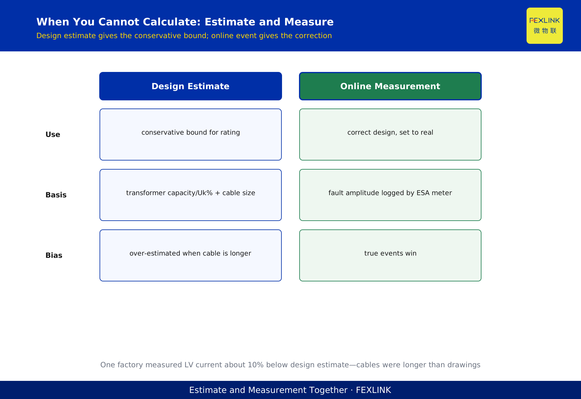
Direct Answer
When you select a circuit breaker, the breaking-capacity row always asks for "prospective short-circuit current." That number is not guessed, and it is not one value for the whole building. Prospective short-circuit current equals the nominal system voltage divided by the total impedance of the short-circuit loop—and that total impedance is a series chain: transformer impedance, busbar impedance, cable impedance, and contact resistance, added segment by segment. The direct consequence is this: the closer you are to the transformer low-voltage side, the larger the short-circuit current; the further you go toward the end feeder, the longer the cable, the higher the impedance, and the smaller the current. In the same panel, the incoming side and the farthest outgoing feeder can differ by several times, so you must calculate point by point, not copy one number across the building.
Why this matters in practice is breaking-capacity selection. If you underestimate the prospective short-circuit current and choose a breaker whose Icu (ultimate short-circuit breaking capacity) is too low, a real short circuit will not clear—contacts weld, or the breaker explodes. If you are overly conservative and apply a high breaking rating to a tiny end feeder, you simply overspend. GB 50054-2011 (Code for design of low voltage electrical installations) requires verifying the breaking capacity of apparatus under short-circuit conditions, and the basis is the prospective short-circuit current at each installation point. Smart meters (such as the ESA full-element meter) and smart breakers (such as the FECB2SP) record the real short-circuit event current, which lets you correct the estimates made at design stage.
1. What This Number Actually Is
Prospective short-circuit current means: at a given point, if a short circuit occurs and the protective device does not act, the steady-state current that would theoretically flow. It is a hypothetical maximum-current baseline, used to verify whether the switches, busbars, and cables at that point can survive it.
On the low-voltage side, what matters most is the three-phase short-circuit current. In engineering you start from the transformer low-voltage bus: divide the nominal voltage (e.g. AC 400 V) by the total loop impedance, and you get the rms value of the prospective short-circuit periodic component at that point. The larger the transformer and the smaller its per-unit impedance Uk%, the larger the low-voltage short-circuit current. The same transformer, with tens of meters of cable at the end, has its end short-circuit current pushed down by the cable impedance.
A common misunderstanding to correct: short-circuit current is not a vague "some multiple of rated current." It is a concrete amperage that varies with installation point. The same 63 A outgoing feeder, measured at the transformer room bus and at the far-end workshop distribution box, can differ five- to tenfold. It decides "how large a breaker rating this point needs," not "how much current flows here normally."
2. Total Loop Impedance: Four Segments in Series
A short-circuit loop is a series impedance chain from the source to the fault point. Split it and there are four main segments.
First, transformer impedance, set by transformer capacity and impedance voltage percentage. It is the largest piece of the chain, and it limits the infinite-system short-circuit current to what the low-voltage side can actually deliver.
Second, busbar impedance. The length and cross-section of main and branch busbars inside the panel set the impedance increment from the transformer low-voltage side to each internal installation point. This segment is usually small, but in large-busbar, high-current panels it cannot be ignored.
Third, cable impedance. From panel to end distribution box, and on to the equipment terminal, the cable is the segment that most often "shrinks" the short-circuit current. The same 95 mm² cable run over 10 m versus 100 m produces a very different end short-circuit current.
Fourth, contacts and contact resistance. Breaker contacts, plug-in connectors, and joint surfaces carry negligible contact resistance under normal load, but inside the short-circuit loop they are still part of the total impedance.
These four segments add in series: total impedance Z = Z_transformer + Z_busbar + Z_cable + Z_contact. Prospective short-circuit current I''k = U / (sqrt(3)·Z). Any impedance in series with the fault reduces the current at that point; any change that lowers impedance (heavier cable, shorter path) raises the end current—which in turn means the minimum end short-circuit current must be large enough for reliable protection.
3. Why the Same Panel Differs So Much: Decay Along the Chain
Draw the impedance chain along the direction of current, and a clear decay curve appears.
At the transformer low-voltage busbar, impedance is smallest and short-circuit current is largest, often in the tens of kiloamperes. At each feeder-breaker location inside the panel, after a length of main busbar, the current drops slightly. Through the outgoing cable to the workshop box, it drops further. At the farthest equipment terminal, where the cable is longest, the current reaches its minimum on the whole chain.
This curve drives two decisions. First, breaking capacity can be selected in tiers: the incoming main switch near the transformer needs a high rating for the maximum current; a small end feeder, whose current has already been squeezed down by cable, does not need the highest rating—just one that meets the calculated value at that point, saving real cost. Second, sensitivity must be checked: the end short-circuit current is small, but it must still be large enough for the local short-circuit protection (instantaneous trip) to act reliably. If the cable is too long and too thin, the minimum end current can fall below the instantaneous pickup, and you get "near-end short circuits clear, far-end ones do not."
One underground garage panel in an industrial park showed exactly this. The incoming main switch was selected at high breaking capacity for about 30 kA at the transformer LV side, but the end lighting feeder, through 80-plus meters of cable, measured under 1 kA. Because the design was not calculated segment by segment, the end switch was also over-rated—wasting money. The subtler problem was an over-high instantaneous setting: a real end short did not trip, and only upstream backup clearing cut the power. Re-deriving from an ESA meter's recorded end-fault current and re-setting against the true decay curve finally fixed the "should act but does not" problem.
4. Two-Phase versus Three-Phase: Which to Calculate
The three-phase short-circuit current is usually the largest, and it is what you use to check breaking capacity and equipment withstand. But engineers must also watch single-phase-to-earth (or phase-to-phase) faults, because end circuits more often see a phase-to-earth fault, and its magnitude decides whether residual-current and instantaneous protection act reliably.
In a TN system, the single-phase fault loop runs through transformer winding, phase conductor, and neutral, so its impedance is not identical to the three-phase loop; in some circuits the single-phase current is actually smaller. So: select breaking capacity against the maximum three-phase current, but check protection sensitivity against the minimum current the point can see (often a remote single-phase fault). Do not mix the two directions.
For terminal products like the FECB2SP smart breaker—covering 1P/2P 16 A/32 A at AC 230 V and 3P/4P 32 A/63 A at AC 400 V with RS485—what you calculate in a 230 V end feeder is the local single-phase prospective current, then compare it to the breaker rating. Do not apply the large panel three-phase number to a 230 V tiny feeder.
5. When You Cannot Calculate: Estimate and Measure Together
Design-stage impedance estimation is the mainstream, but on site you rarely get exact cable lengths and busbar data, so estimation error is real. Direct measurement is a good complement.
One method is back-calculating from the upstream rating: given the transformer capacity and impedance, first compute the LV-side current, then scale down by the local cable cross-section and length to the end value. Another is using online monitoring data: the ESA full-element meter records voltage, current, and other electrical quantities; the digital electrical supervision system aggregates them. When a real short or large fault current happens on site, the recorded amplitude is the most direct measured value of the prospective current at that point.
This dual track—design estimate plus event measurement—is valuable: the estimate gives the conservative upper bound for selection, and the measurement gives the correction basis. Two years after energizing, one factory substation's platform held records from several large-motor starts and one near-area fault. Back-derivation showed the actual LV short-circuit current was about ten percent lower than the design estimate—the installed cables were longer than the drawings. After correcting to measured values, later feeder selections matched real conditions: neither risky nor wasteful.
6. After You Calculate: Select Breaking Capacity and Re-Check Online
Once you have the prospective current at each point, the landing point is the breaker's Icu. The principle is simple: the local prospective short-circuit current must not exceed the breaker's Icu, with margin. The main switch near the transformer takes a high rating; end feeders take their point value, not the largest available.
But one calculation is not forever. Park expansion, new transformers, and large loads change the loop impedance, and the prospective current changes with it. That is exactly the value of online monitoring: the FECB2SP uploads each short-circuit trip's instantaneous current and time to the platform; the ESA meter records loop quantities; the supervision system continuously compares "what the design calculated" with "what actually occurred." When expansion raises the system short-circuit level, the platform flags breakers whose breaking margin is narrowing, so you re-check in advance instead of discovering during a short that the switch cannot hold.
Remember this: prospective short-circuit current is a position function that decays along the impedance chain, not one constant for the whole building. Calculate segment by point, select breaking capacity by point, and keep re-checking through online events.
Scope and Limits
This article targets low-voltage 380/220 V AC distribution in TN systems and explains the calculation logic and engineering method; it does not replace a formal short-circuit calculation report. Actual calculations must use real transformer parameters, cable lengths and cross-sections, and busbar layout. Product parameters of FECB2SP and ESA and vendor-disclosed typical magnitudes are used to illustrate method; on-site selection must be checked against product datasheets and current codes such as GB 50054-2011. Short-circuit calculation and protection setting must be performed by qualified electrical design engineers.