 微物联研究院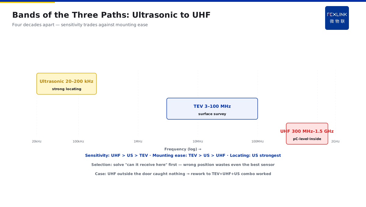
Direct Answer
UHF, ultrasonic, or TEV for switchgear PD monitoring? The answer: they capture different propagation components of the same partial-discharge event — UHF catches the radiated electromagnetic wave (highest sensitivity, but blocked by the metal enclosure); ultrasound catches mechanical vibration (best for surface discharges and locating); TEV catches the cabinet's induced pulses (surface-mounted, no outage needed). There is no "best" method — only "which one first, which one supplements."
A distribution room tendered PD monitoring and got three very different quotes: UHF sensors at nearly ten thousand yuan each, ultrasonic at a few hundred, TEV around two thousand. The owner picked the "most expensive full UHF package" — and it worked badly. The switchgear is metal-enclosed; with UHF sensors mounted outside the cabinet door, the electromagnetic wave was shielded and internal PD was never picked up. They reworked the design into "TEV survey across all cabinets + built-in UHF on key cabinets + ultrasonic for locating" — and only then did PD monitoring actually work.
Because:
- One discharge produces three components: a radiated electromagnetic wave (UHF), mechanical vibration (ultrasonic), and induced cabinet current (TEV);
- Propagation path decides sensor position: EM waves fear shielding, sound fears air gaps, induced pulses are picked up right on the cabinet surface;
- The three methods complement each other: UHF is most sensitive for internal discharges, ultrasound for surface discharges and locating, TEV for outage-free whole-cabinet surveys;
- Selection is not about price: first know your switchgear type, your goal (survey or pinpoint), and whether an outage is possible.
Key insight: PD monitoring is not "buy the most expensive sensor and mount it"; it is "send each propagation component home." Combined use covers defects at different locations.
An airport surveyed 86 cabinets of 10 kV switchgear with TEV on the cabinet surface, flagged 7 with abnormal levels, confirmed 2 with internal discharges using built-in UHF probes, and located the exact gas chamber with ultrasound. Three checks cross-validated each other, and only those 2 cabinets were taken out for maintenance — far cheaper than opening every cabinet.
1. Three Propagation Paths of the PD Signal
A partial discharge occurs at an internal insulation defect. At the discharge instant, three physical quantities are generated simultaneously:
1. Radiated electromagnetic wave (UHF)
- The discharge current pulse radiates EM waves at 300 MHz–1.5 GHz;
- Propagation is near light speed (3×10⁸ m/s), line-of-sight through the air inside the cabinet;
- Strength: richest amplitude information — pC-level discharges are measurable;
- Weakness: the metal enclosure is a natural shield — the signal cannot leave the cabinet; the sensor must go inside or hug a gap.
2. Mechanical vibration (ultrasonic)
- Discharge energy becomes elastic waves at 20–200 kHz (40 kHz center frequency is common);
- Propagation speed is ~5000 m/s in metal, ~340 m/s in air/insulation — the difference enables locating;
- Strength: strong directionality — can pinpoint a gas chamber or a connector;
- Weakness: air gaps attenuate the signal; discharges inside sealed insulation cannot get sound out.
3. Cabinet-induced pulse (TEV)
- The discharge induces a pulse current on the inner metal surface that travels along the cabinet shell;
- Frequency content roughly 3–100 MHz, amplitudes in mV;
- Strength: a sensor stuck on the outer surface picks it up — no outage, no opening;
- Weakness: the signal is indirect — "yes/no" detection only; weak at locating and quantifying.
Key insight: one discharge produces all three components simultaneously, but with different paths, attenuation, and reachable locations. Where you mount the sensor and what type it is decide which component you see.
2. Frequency Band and Sensitivity Comparison
The three paths differ completely in frequency band, medium, sensitivity, and application:
| Method | Band | Medium | Sensitivity | Locating | Outage-free |
|---|---|---|---|---|---|
| UHF | 300 MHz–1.5 GHz | air/insulation in cabinet | highest (pC-level) | poor (no direction) | needs opening/built-in |
| Ultrasonic | 20–200 kHz | metal/solid | medium (mV vibration) | strong (time-difference) | gap-mount only |
| TEV | 3–100 MHz | cabinet metal surface | medium-low (mV) | weak (level only) | surface-mount only |
Selection logic:
- New cabinets, outage possible, maximum sensitivity wanted → built-in UHF (expensive, hard to service later);
- Surface discharges, loose connectors, locating needed → ultrasonic (cheap, portable);
- Existing cabinets, no outage, whole-fleet survey → TEV (surface mount, moderate cost).
Key insight: the higher the sensitivity, the tighter the mounting constraint. UHF is the most sensitive but useless if it cannot get inside the cabinet; TEV is the least sensitive but works the moment it is stuck on. On-site selection must first solve "can the sensor physically receive the signal," then talk sensitivity.
3. Which Defect Type Each Method Excels At
Different defect locations produce different component strengths — that decides which method is most sensitive to that defect:
1. Internal insulation discharge (voids, impurities, delamination) → UHF excels
- The discharge is inside the insulation; EM waves propagate through insulation and air gaps, where UHF is most sensitive;
- Typical scenes: cable termination voids, internal defects in cast epoxy insulation;
- Recommendation: built-in UHF on key cabinets, or gap-mounted UHF antennas.
2. Surface discharge (tracking, creeping flashover) → ultrasonic excels
- The discharge sits on an insulation surface or in air; sound radiates directly into air;
- Typical scenes: polluted insulator tracking, along-surface discharge at busbar support insulators;
- Recommendation: point the ultrasonic sensor at the discharge area; works with handheld patrol.
3. Connector discharge (poor contact, sharp edges) → TEV + ultrasonic combined
- Discharge is near metal connections; cabinet induced pulses are clear and TEV screens fast;
- Typical scenes: loose busbar bolts, bad HV cable joints, poor grounding;
- Recommendation: TEV fleet survey to flag, ultrasonic to pinpoint.
4. Locating scenarios → ultrasonic time-difference method
- Several ultrasonic sensors measure arrival-time differences of the same discharge and reverse-compute the source;
- 5000 m/s in metal vs 340 m/s in air gives good resolution;
- Typical scenes: locating PD inside a GIS chamber, inside a switchgear busbar compartment.
Key insight: "which method is better" depends on "which defect you suspect." When the defect type is unknown, survey with TEV first to narrow the range, then confirm with UHF/ultrasonic.
4. On-Site Convenience Without Outage
Operators care most about "can we do it without an outage." The three methods differ sharply:
TEV: most convenient — just stick it on
- Magnetic/adhesive mount on the outer cabinet surface; no outage, no opening;
- One handheld TEV unit can scan dozens of cabinets per shift;
- For: annual surveys, patrols, quick checks.
Ultrasonic: next — just approach a gap
- Point the sensor at door gaps or cable-compartment gaps to receive;
- While scanning, use earphones to judge the "hissing" manually;
- For: key-point patrol, verifying suspects, locating.
UHF: least convenient — must go inside
- Built-in probes need an outage to install; external antennas must also face gaps/inspection windows;
- Once installed, later maintenance needs an outage;
- For: pre-embedded in new cabinets, long-term monitoring of key cabinets.
Key insight: convenience and sensitivity are a trade-off. Survey with TEV (easy but coarse), pinpoint with UHF (sensitive but troublesome); ultrasonic sits in between — organize the site plan "coarse first, then fine."
5. Combined Monitoring Configuration
A sound PD monitoring scheme is not "pick one of three" but "combine all three, layered by role":
Configuration (investment low to high):
- Base layer (required): TEV sensors on every cabinet surface, feeding the monitoring system for whole-fleet online survey;
- Key layer (optional): built-in UHF probes on critical-load and historically-problematic cabinets for long-term high-sensitivity monitoring;
- Locating layer (on demand): portable ultrasonic instrument, used to pinpoint after an anomaly; not installed online.
Data flow: TEV online survey → platform flags an abnormal cabinet → ultrasonic pinpoints at the cabinet → UHF re-checks and quantifies → verify during the scheduled outage. Every layer has a clear role — no overlap, no waste.
Note: TEV signals are easily disturbed externally (nearby switching, lightning). Combine phase recognition and repetition-rate filtering to avoid false alarms — exactly where platform algorithms earn their keep.
6. Product Landing: PD Monitoring in the Digital Electrical Intelligent Supervision System
FEXLINK's Digital Electrical Intelligent Supervision System integrates all three sensor types:
- TEV / ultrasonic / UHF sensors form the sensing layer, converging on the edge computing gateway;
- The platform performs cross-validation across the three signals: TEV abnormal but UHF silent suggests external interference; both abnormal almost confirms internal discharge;
- Phase recognition and repetition-rate analysis (Tianyan engine) separates "background noise / genuine discharge / external interference";
- Alarms are pushed by grade (Qianzhi alarm engine): single TEV point elevated → watch; UHF-confirmed discharge → schedule the outage repair.
Design principle in one sentence: the sensor makes it receivable; the platform makes it correct. Any single sensor type misjudges easily; cross-validation across signal types is what makes judgment reliable.
7. Common On-Site Mistakes
- Choosing UHF by price alone: mounted outside a metal-enclosed cabinet, the signal is shielded and never received. Consequence: most money spent, worst result. Correct: first confirm the sensor can reach a location where the signal can arrive.
- Installing only one sensor type: internal discharges are invisible to ultrasound (sound cannot escape sealed insulation) — a false "no PD." Consequence: defects missed. Correct: combine by defect type.
- TEV mounted in the wrong place: on door hinges or poor grounding, signal attenuates or picks up interference. Consequence: missed or false alarms. Correct: mount on a flat mid-panel surface, away from vents and hinges.
- Treating one high pulse as an alarm: switching or lightning produces one tall interference pulse — mistaken for PD. Consequence: alarm fatigue. Correct: judge by repetition rate and trend, not single peak.
- Measuring without recording: handheld patrols leave no baseline, so next time nothing compares. Consequence: trend judgment impossible. Correct: record a baseline every patrol and build an amplitude trend curve.
Scope and Limitations
This article discusses selection principles for three PD detection paths in MV switchgear, applicable to 10 kV/35 kV metal-enclosed switchgear, ring main units, and GIS. Specific sensor models, mounting methods, and thresholds follow equipment manuals and on-site tests. GIS internal discharge locating involves complex acoustic propagation and should incorporate specialist testing conclusions. All cases are anonymized (a certain airport / distribution room) and do not refer to any specific customer.