 微物联研究院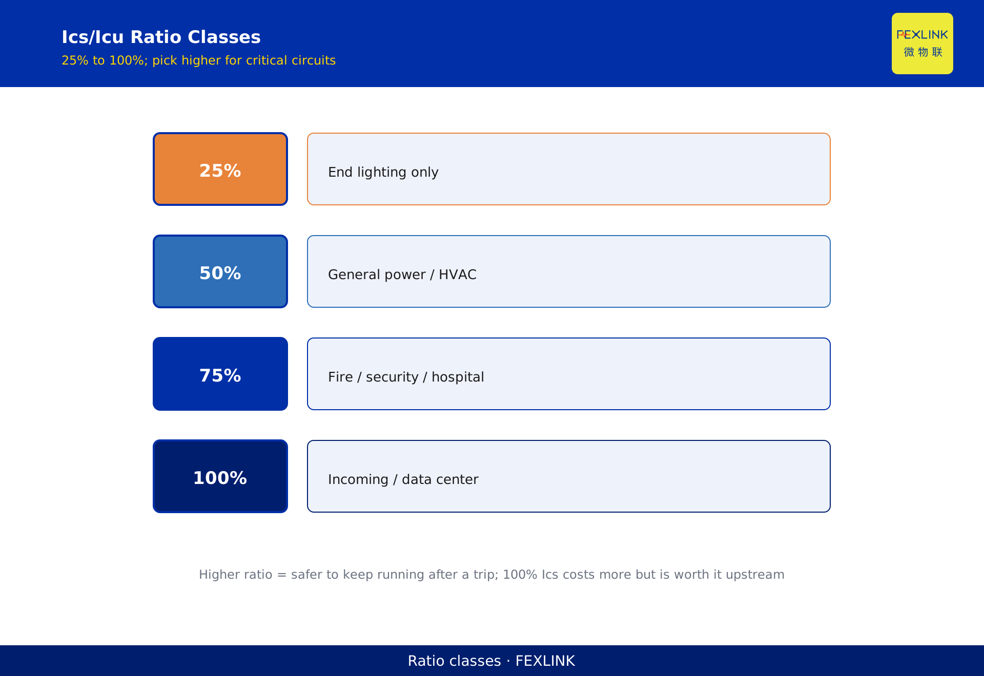
Direct Answer
Icu is the ultimate short-circuit breaking capacity; Ics is the service short-circuit breaking capacity. Both matter, but they mean different things. Icu guarantees the switch can clear the fault without exploding; Ics determines whether the switch can keep running after that clearance. The sizing rule is simple: first make Icu ≥ the prospective short-circuit current Isc at the installation point, then pick a high Ics/Icu ratio for critical circuits. Selecting a breaker only by rated current is the root cause of "switch exploded on fault" or "switch was junk after one trip."
In a basement incoming cabinet of a Grade-A office building, the prospective fault current was 28 kA but the design picked an MCCB with Icu=25 kA. When a short circuit occurred, the switch barely cleared it; the contacts were so eroded that the next fault would have meant failure to trip. Replacing the switch took eight hours and darkened a whole floor. The problem was not the brand—it was that nobody checked Icu.
1. What the Numbers on the Nameplate Actually Mean
A breaker nameplate commonly reads In=63A / Icu=35kA / Ics=26kA. Many engineers look only at 63 A and skip the two kA values.
- In: rated current; the continuous current the breaker can carry.
- Icu (Ultimate Short-Circuit Breaking Capacity): the maximum fault current the breaker can clear. After clearing at this level, continued operation is not guaranteed—contacts may be eroded and service or replacement is required.
- Ics (Service Short-Circuit Breaking Capacity): a fault current level the breaker can clear and still carry rated current afterward, without immediate replacement.
GB/T 14048.2 rates Ics as a percentage of Icu: 25%, 50%, 75%, 100%. For a 35 kA Icu breaker, 17.5 kA Ics is the 50% class; 35 kA Ics is the 100% class.
2. Why the Ics/Icu Ratio Determines Whether the Switch Survives
Clearing a short circuit is not "cut it and done." Fault current peaks are enormous; contacts part in milliseconds under severe arc erosion.
- Fault current between Ics and Icu: the switch clears it, but contacts are damaged. The next fault of similar magnitude may see reduced breaking capacity or even failure to trip. Engineering practice requires inspection or replacement.
- Fault current within Ics: contact erosion stays within design margin; the breaker can keep carrying load and protecting the circuit.
For ordinary lighting and socket circuits, replacing a switch after a fault is a minor nuisance. But for data centers, hospital operating rooms, and continuous production lines, you cannot afford an eight-hour outage because the breaker was destroyed. These circuits must use a high Ics/Icu ratio—preferably 100%.
3. Two-Step Selection
Step 1: calculate the prospective short-circuit current Isc from transformer capacity, cable length, and impedance at the installation point. This sets the lower bound for Icu.
Step 2: choose Icu ≥ Isc, then select the Ics class.
- Ordinary end-circuit lighting/sockets: Icu sufficient, Ics 50% class is fine.
- Critical loads (fire safety, security, hospitals, data centers, continuous process): Ics/Icu ≥ 75%, key circuits at 100%.
- Main incoming and bus-tie: prefer 100% Ics, because a failed upstream breaker causes the largest outage footprint.
Do not look only at frame size. Two 630 A MCCBs can have Icu ratings from 35 kA to 65 kA—the price difference is real, but the cost of choosing wrong is a cabinet fire.
4. Three Common Pitfalls
Pitfall 1: Icu too small. Site fault current is 40 kA; the selected Icu is 35 kA. The switch cannot clear the fault, the arc burns through the enclosure, and the cabinet explodes.
Pitfall 2: Ics too small. Icu is adequate but Ics is only 25%. One fault trip destroys the switch; maintenance blames "quality" when it was never specified.
Pitfall 3: upstream/downstream Icu mismatch. The downstream Icu exceeds the upstream one—if the lower breaker cannot clear, the upper one cannot either. This is coordination, not a single-switch problem.
5. Where FECB2SP Fits
The FEXLINK FECB2SP smart breaker covers 1P/2P 16 A/32 A AC 230 V and 3P/4P 32 A/63 A AC 400 V, with RS485 integration. Its role is not to replace high-breaking MCCBs, but to record the current peak and operating time at the moment of clearance. After a fault trip, maintenance does not have to guess how large the short-circuit current was or how fast the switch acted—the backend data shows it, and engineers can decide whether the breaker needs inspection or an Ics upgrade.
For an installed power system, this is a low-cost way to do post-hoc verification: collect real fault waveforms and confirm whether the original Icu/Icu sizing was adequate.
6. One Table to Remember
| Scenario | Icu requirement | Recommended Ics/Icu |
|---|---|---|
| Ordinary lighting/socket end-circuits | ≥ Isc | 50% |
| General power / HVAC | ≥ Isc | 75% |
| Fire safety / security / hospital | ≥ Isc with 1.2× margin | 100% |
| Incoming / bus-tie / data center | ≥ Isc with 1.2× margin | 100% |
7. Why the Ics/Icu Ratio Matters
A reader may ask: if Icu is enough, why bother with Ics?
Because after a short-circuit trip, do you still want to use this breaker?
Icu sufficient but Ics low: a short occurs — the breaker clears it — but the contacts are burned. You must replace the breaker — hours of downtime.
Icu sufficient and Ics high: a short occurs — the breaker clears it — contacts are undamaged — keep using it.
For a normal lighting circuit: replacing a breaker is no big deal — one hour downtime. For a data center: replacing a breaker = four hours downtime = millions in losses.
That is why critical circuits choose 100% Ics/Icu — after a short, no replacement needed, keep running.
8. Common Questions
Q: What if I choose a breaker with Icu just equal to the calculated short-circuit current? A: That is the minimum. Add a margin — at least 20% above calculated Isc. Standards recommend Icu ≥ Isc with a safety factor.
Q: Can I upgrade Ics later by changing the breaker? A: Yes, but that requires a planned outage. It is much cheaper to choose the right Ics rating at the start.
Q: Does the FECB2SP report Ics/Icu? A: The FECB2SP records every trip event with peak current and clearing time. After a real short, you can review whether the breaker survived intact — data-driven verification.
9. A Real-Life Case
An office building upgraded its main switchboard. The incoming MCCB was selected with Icu = 36 kA, matching the calculated short-circuit current of 32 kA. The Ics/Icu ratio was 50%.
Two years later, a downstream short occurred. The breaker tripped correctly, but on inspection the contacts were severely eroded. The breaker had to be replaced — two hours of downtime for the entire floor.
Had the engineer chosen a 100% Ics/Icu breaker at the start, the contacts would have survived and the building could have kept running. The replacement cost was not just the breaker itself — it was the downtime, the technician callout, and the tenant complaints.
Lesson: for critical circuits, paying 20% more for a higher Ics rating upfront saves ten times that in downtime after a real short.
10. How to Read the Nameplate
A breaker nameplate has several numbers. Here is what each one means:
- In: rated current. The continuous current the breaker can carry.
- Icu: ultimate short-circuit breaking capacity. How much short-circuit current it can break once — after that, it may be damaged.
- Ics: service short-circuit breaking capacity. How much short-circuit current it can break and still continue to use.
- Icm: making capacity. How much peak current it can close onto (against a short that is already there).
Ics/Icu ratio tells you the "reusability" after a fault. A 100% ratio means the breaker is as good as new after breaking a short. A 25% ratio means it can only handle a small short and still keep working.
11. One Sentence to Remember
Icu tells you if the breaker can break the short. Ics tells you if it can keep working afterward. For critical circuits, Ics matters as much as Icu.
12. Quick Checklist
Before finalizing a breaker selection:
- Calculate the expected short-circuit current at the installation point.
- Choose Icu ≥ calculated Isc with at least 20% margin.
- Check the Ics/Icu ratio — for critical circuits, aim for 100%.
- Verify the upstream/downstream coordination.
- Record the selected model and ratings in the design document.
Scope and Limitations
This article applies to GB/T 14048.2, low-voltage switchgear and controlgear—part 2: circuit breakers. Icu/Ics values follow the nameplate and datasheet of the specific model; the same frame size from different manufacturers can differ substantially. The office building mentioned above is an anonymized example. FECB2SP targets small end-circuits; high-current incoming applications still require upstream MCCB selection.