 微物联研究院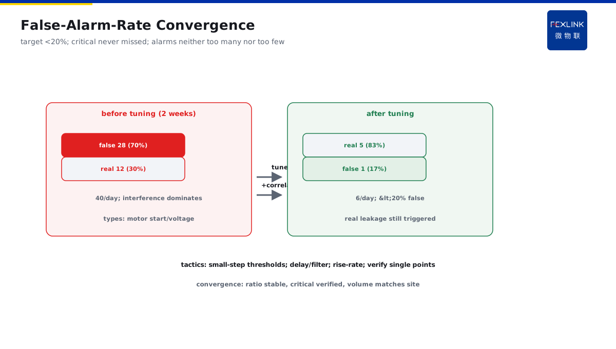
Direct Answer
After the system goes live with default thresholds, alarms keep coming and operations staff do not know how to tune them on site. The answer: a three-step convergence — first set initial lower limits per national standards and codes; run for two weeks to collect actual alarms and calculate the false-alarm ratio; fine-tune thresholds and add correlation conditions (e.g., temperature + leakage together) by the false-alarm ratio; the tuning goal is "critical signals never missed, obvious interference not reported," not zero alarms.
At one industrial park's electrical-monitoring system going live: initial thresholds were set per the standard lower limits (temperature 70°C warning, leakage 300mA); after two weeks of statistics: 40 alarms/day on average, 28 false (70%), mostly motor-start transient interference. Fine-tuning: temperature warning raised to 75°C, adding "sustained 10 s + temperature-rise rate" correlation; leakage alarm adding "correlation with voltage fluctuation." After tuning: 6 alarms/day on average, and a real leakage was not missed. Tuning core: initial lower limits → two-week statistics → false-alarm-rate fine-tuning — data-driven convergence, no misses, no floods.
Because:
- Initial thresholds need a basis: national standards and codes give lower limits, avoiding guesswork;
- Two-week data is the "tuning sample": alarm types and frequencies must be counted before the problem is known;
- The false-alarm rate is the "convergence indicator": fine-tune thresholds and correlation conditions by its proportion;
- The goal is not zero alarms: the point is no missed signals and no interference reports.
Key insight: "set lower limits first, then converge with data" is the right path for threshold tuning. Two-week samples + false-alarm-rate fine-tuning — alarms neither too many nor too few, and the must-report always reports.
At one plant, thresholds were set extremely high (for quietness): temperature warning 95°C, leakage 500mA. For three months, no cable-heating alarm was triggered (actual temperature had risen to 88°C); it was found only by manual inspection. Rectification: re-set per the standard lower limits and fine-tuned with two weeks of statistics. Lesson: chasing quietness causes missed alarms — "critical signals not missed" is the bottom line; false alarms are solved by data convergence, not by raising thresholds to escape.
1. Code Basis for Initial Thresholds
Step one: how to set the starting point.
Normative sources:
- National/industry standards: limits for temperature, leakage, PD, etc.;
- Equipment manuals: manufacturer-recommended operating ranges;
- Similar-project experience: tuned values for comparable scenarios;
- On-site conditions: load characteristics, ambient-temperature correction.
Common initial lower limits:
- Temperature warning: 80% of the equipment's allowable upper limit (e.g., 90°C limit → 72°C warning);
- Temperature alarm: near the upper limit (e.g., 85°C);
- Leakage alarm: 30mA (personal safety) / 300mA (insulation anomaly);
- PD warning: by equipment type and voltage level (refer to industry experience values).
Setting principles:
- Start from the "code lower limit" (prefer more alarms over missed ones);
- Condition correction: adjust for high-temperature/heavy-load scenarios;
- Graded settings: warning/alarm two levels (warning for early notice, alarm for strong response);
- Record the basis: note the threshold source (code/manual/experience).
Key insight: initial thresholds are "strict rather than loose." Start from the code lower limit — more alarms can be converged; missed alarms hurt safety.
2. Two-Week Data Collection Method
Step two: how to collect the sample.
Content to collect:
- Alarm time/point/type;
- Load and conditions at alarm time;
- On-site verification result (real or false);
- Alarm duration and frequency.
Collection method:
- Export platform alarm records (time series);
- On-site checks (sample verification of truth);
- Condition records (load/weather/operation events);
- Interference-source identification (motor starts/operations/weather).
Two-week sample size:
- Cover working days + weekends (different loads);
- Cover typical conditions (normal/maintenance/start-up);
- Cover seasonal variation (extend if possible);
- Statistics dimensions: by point/type/time period.
Statistical outputs:
- Average daily alarms (total);
- False-alarm ratio (false/total);
- False-alarm type distribution (interference/threshold/correlation-missing);
- Real-alarm list (critical-signal confirmation).
Key insight: two-week data is the tuning sample. Record + verify + classify — once the alarm pattern is counted, convergence has a basis.
3. False-Alarm-Rate Statistics and Fine-Tuning
Step three: how to tune.
False-alarm-rate calculation:
- False-alarm rate = false alarms ÷ total alarms;
- Target: reduce below 20% (experience value);
- Critical signals: no real alarm missed (bottom line).
Fine-tuning strategies:
- False alarms concentrated near a threshold: fine-tune the threshold (small steps);
- Interference-type false alarms (start/operation): add delay/filtering;
- Environmental false alarms (temperature fluctuation): add temperature-rise-rate judgment;
- Point-type false alarms (one point high): verify that point alone (sensor/location).
Adjustment principles:
- Small-step fine-tuning (5%–10% each time), observe two weeks before tuning again;
- Adjust by level (warning/alarm separately);
- Record every adjustment (basis + result);
- Adjust single-point issues individually (no blanket changes).
Convergence judgment:
- False-alarm rate falls and stabilizes (two statistics converge);
- Critical signals still trigger (no-miss verification);
- Alarm volume matches the actual site (neither too many nor too few).
Key insight: the false-alarm rate is the convergence dashboard. Small steps + observation periods — below 20% with no missed critical signals means done.
4. Adding Correlation Conditions
Step four: how to reduce interference false alarms.
Correlation-condition principle:
- Single-indicator alarms are prone to interference (start/fluctuation);
- Multi-indicator correlation (temperature + leakage / temperature + rate) filters interference;
- Time-series correlation (sustained N seconds) avoids transient false alarms;
- Condition correlation (load/operation) excludes normal fluctuation.
Common correlations:
- Temperature + sustained 10 s (filters start transients);
- Temperature + temperature-rise rate (identifies real heating);
- Leakage + voltage stability (excludes voltage-fluctuation interference);
- PD + trend (multi-event confirmation, not single-shot).
Implementation:
- Platform interlock rules (multi-condition AND);
- Delay confirmation (alarm acknowledgment time);
- Trend judgment (slope/cumulative);
- Condition marking (operation windows: no report or downgraded).
Notes:
- Over-strict correlation causes missed alarms (real anomalies filtered out);
- Correlation conditions need a physical basis (why they are correlated);
- Keep critical-signal loops simple (safety first);
- Verify: simulate triggers after adjustment (confirm alarms still work).
Key insight: correlation conditions are the interference filter. Temperature + rate + duration + condition — multi-condition confirmation reduces false alarms without missing real ones.
5. Tuning Records and Re-Evaluation Cycle
Step five: how to close the loop.
Tuning records:
- Threshold initial/adjusted values and basis;
- Two-week statistics (false-alarm-rate change);
- Correlation-condition settings and verification results;
- Adjuster/date/notes.
Re-evaluation cycle:
- Re-evaluate 1 month after first tuning (stability confirmation);
- Seasonal re-evaluation (summer heat/winter);
- Re-evaluate on condition changes (load/equipment retrofit);
- Re-evaluate after new equipment (new-point tuning).
Continuous optimization:
- Monthly review of alarm trends (maintain the false-alarm rate);
- Identify new interference sources (continuous collection);
- Aging review of thresholds (equipment aging may require adjustment);
- Link with maintenance (inspection results feed threshold reasonableness).
Key insight: records and re-evaluation guarantee the closed loop. Adjustment trace + periodic review — thresholds stay reasonable, no misses and no floods in the long run.
6. Product Landing: Digital Electrical Intelligent Supervision System
FEXLINK products land threshold tuning:
- Graded thresholds: warning/alarm two-level configuration;
- Data statistics: alarm-record export and false-alarm-rate reports;
- Correlation rules: multi-condition interlocking (temperature + rate + duration);
- Re-evaluation reminders: periodic tuning review and records.
Design principle in one sentence: "set lower limits first, converge with data, review in a closed loop." Initial basis + two-week samples + false-alarm-rate fine-tuning — alarms neither missed nor flooded.
Common scenario Q&A:
- Q: No real alarm in two weeks — how to tune? A: First confirm the system is normal (there may genuinely be no anomaly); meanwhile run trigger tests (simulate over-limit) to verify the alarm path, avoiding an "unknown broken path."
- Q: One point always false-alarms while others are normal? A: Single-point issues checked individually — first verify the sensor/location/wiring, then adjust only that point's threshold; no blanket changes.
- Q: The false-alarm rate will not come down? A: First classify the false-alarm types (interference/threshold/correlation-missing), then address the dominant cause: add delay and correlation for interference, fine-tune thresholds by statistics, add conditions for missing correlation.
- Q: Can I tune the thresholds to satisfaction in one pass? A: Not recommended — large steps tend to over-converge and cause missed alarms; small steps with two-week observation are more stable.
- Q: More false alarms after the season changes? A: Normal — summer heat raises environmental noise; re-evaluate quarterly and add temperature-rise-rate/condition correlations for environmental false alarms.
7. Common Tuning Misconceptions
- Raising thresholds for quietness: temperature set to 95°C. Consequence: real anomalies not reported. Correct: standard lower limits + data convergence.
- No two-week collection: tuning by feel. Consequence: wrong direction. Correct: count the false-alarm ratio first.
- One-size-fits-all: one threshold for all points. Consequence: false/missed alarms on points with different conditions. Correct: adjust single-point issues individually.
- Large jumps: 30% at once. Consequence: over-convergence causes missed alarms. Correct: small steps + observation periods.
- Threshold-only, no correlation: ignoring the nature of interference. Consequence: repeated false alarms. Correct: add correlation conditions to filter interference.
Scope and Limitations
This article provides a three-step convergence method for on-site alarm-threshold tuning (code basis, two-week data collection, false-alarm-rate fine-tuning, correlation conditions, records/re-evaluation) for threshold tuning and alarm management after an electrical-monitoring system goes live. Specific threshold values must be determined by equipment type, voltage level, on-site conditions, and applicable codes; correlation conditions must have a physical basis and be verified not to miss alarms; tuning and re-evaluation must be performed by operations staff per procedures. All cases are anonymized (a certain industrial park/a certain plant) and do not refer to any specific customer.