 微物联研究院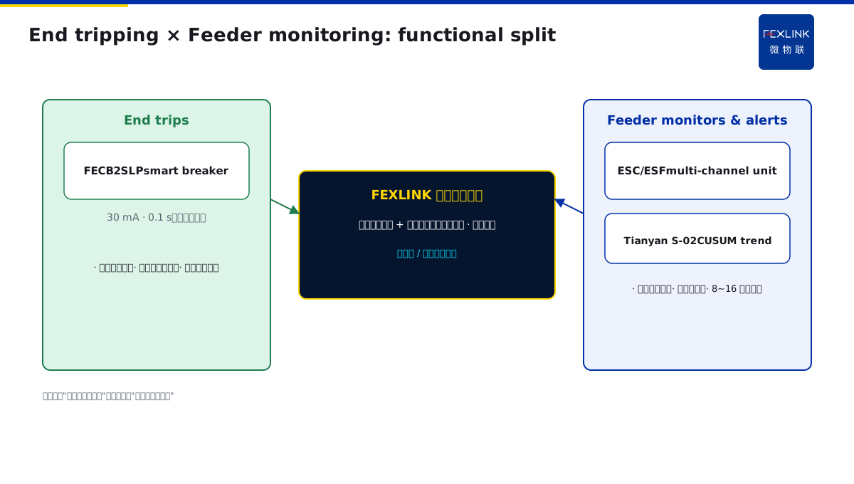
Direct Answer
Residual-current protection must not be installed at the main incoming point alone. The correct practice is graded installation: 30 mA high-sensitivity fast RCDs at the end of the circuit (sockets, hand-held tools, wet areas) to protect people; 300 mA time-delayed RCDs on floor and feeder levels to prevent electrical fire. Selectivity between stages is achieved by a time grading scheme (0.1 s at the end, 0.3 s on the floor, 0.5 s at the main incoming) so that the downstream device trips first and upstream devices do not over-trip. The FECB2SLP smart breaker with residual-current function sits at the end to trip, while multi-channel residual-current monitors (ESF/ESC) sit on the feeder for continuous measurement and alarm.
1. Why a single main RCD always fails
Many drawings put one 400 A residual-current breaker at the LV main incoming and let it protect the whole building. After six months two pathologies appear:
- Sensitivity tuned high: at 100 mA, the aggregated leakage of lighting, HVAC and IT loads in a whole building often approaches this threshold, and on humid rainy days nuisance tripping is daily—until the O&R team disables the device.
- Sensitivity tuned low: at 500 mA or 1 A, when a person in the bathroom touches 230 V, the current may need to build up to 500 mA before tripping—the person may already be injured or unconscious.
The root conflict is that personal protection needs mA level within 0.1 s, while fire protection needs amperes and tolerates delay. These two goals cannot be met by a single breaker. GB/T 13955 explicitly requires graded protection; it is not optional.
2. End-of-circuit 30 mA: protect people, trip as fast as possible
End circuits include:
- Domestic socket circuits and portable power tools;
- Bathrooms, kitchens, balconies and other wet locations;
- Outdoor temporary supplies and construction sites;
- Hospitals, schools, nursing homes and other densely occupied spaces.
Required RCD parameters at this level:
| Parameter | Requirement | Note |
|---|---|---|
| Rated residual operating current IΔn | ≤30 mA | Human safety threshold |
| Breaking time | ≤0.1 s (Type AC) | Fast type, no delay |
| Type | Type A or AC | Type A mandatory on VFD-fed circuits |
| Location | Terminal distribution board | One RCD per circuit group |
The FECB2SLP smart breaker with residual-current function belongs at this level. Beyond tripping, it uploads residual-current value, trip count, internal temperature and contact status via RS485, so O&R no longer has to guess "why did it just trip".
3. Feeder 300 mA: fire protection, delay allowed
At floor distribution boards, riser busways and workshop incoming, the protected object shifts from "people" to "cables and equipment". Requirements:
- IΔn set to 300 mA, mainly to prevent electrical fire caused by insulation ageing and earth leakage;
- Tripping time 0.3–0.5 s delayed type, deliberately slower so the end device trips first;
- Instantaneous cut is not required; alarm followed by manual confirmation is acceptable;
- RCDs at this level carry larger currents and have higher thresholds, so they are not triggered by end-circuit noise.
4. How to set the time grading so upstream does not over-trip
Selectivity relies on time grading. A typical scheme:
End (socket circuit): IΔn = 30 mA, t = 0.1 s Floor (riser): IΔn = 300 mA, t = 0.3 s Main incoming (LV cab):IΔn = 500 mA, t = 0.5 s
On an earth fault, current propagates upstream from the fault:
- The end RCD trips within 0.1 s, isolating the faulted circuit;
- The floor RCD at 0.3 s waits 0.2 s in case the end device has not responded;
- The main incoming at 0.5 s is the last line, and trips only when both downstream stages have failed.
As a result, the fault is confined to the smallest circuit—no more "one socket leaks, the whole floor goes dark".
5. How smart monitoring closes the blind spots of traditional RCDs
A traditional RCD is binary: trip or not trip, with everything in between left to guesswork. FEXLINK practice is to add on the feeder:
- ESF electrical fire monitor: continuous residual-current, cable temperature and arc measurement with trend logging;
- ESC multi-channel residual-current unit: one device covers 8–16 circuits, ideal for floor distribution boards;
- Tianyan S-02 CUSUM engine: accumulates residual-current trend and alarms early as leakage slowly climbs, long before it reaches 300 mA.
This set pairs with end RCDs: end devices cut when a fault has already occurred; feeder monitors warn before a fault develops.
6. One table to recall the graded scheme
| Stage | Location | IΔn | Time | Purpose | Recommended product |
|---|---|---|---|---|---|
| End | Socket / hand-held / wet | 30 mA | 0.1 s | Personal protection | FECB2SLP smart breaker |
| Floor | Riser / sub-DB | 300 mA | 0.3 s | Fire + selectivity | Delayed RCD + ESC |
| Main incoming | LV switchboard | 500 mA | 0.5 s | Last defence | Smart air circuit breaker |
| Monitoring | Along feeder | Continuous | Real-time | Trend early-warning | ESF + Tianyan S-02 |
7. Three common wrong practices
- 30 mRCD at the main incoming: aggregated building leakage guarantees nuisance trips, and the device ends up bypassed.
- 300 mA delayed RCD at the end: too slow to save a person touching live parts; personal protection is lost.
- RCD without monitoring: no data during slow insulation ageing; when the breaker finally trips, smoke is often already visible.
The correct engineering habit is: configure RCDs by grade per the table, then add continuous monitoring on the feeder, and finally bring all leakage data together on a platform.
8. Why 30 mA at the End and 300 mA on the Main Cannot Be Swapped
Some people ask: can I just use 30 mA everywhere? Why must the main be 300 mA?
The reason is the balance between nuisance tripping and coverage.
End circuits: only a few sockets, a few lights. Short cables, small leakage. 30 mA setting is just right — trips in 0.1 second when a person gets shocked.
Main circuits: hundreds of end circuits. Long cables, large capacitance to ground. Normal leakage can already be 100 mA. If the main is also set to 30 mA, it will trip every day — the whole floor goes down.
So the分级 is: end sensitive (protect people), main not sensitive (prevent fire without nuisance tripping). This is physics, not opinion.
9. One Sentence to Remember
RCD grading is not optional. It is required. 30 mA at the end protects people. 300 mA on the main prevents fire. Swap them and you get neither.
10. Common Questions
Q: Can I use 30 mA on everything to be safer? A: No. You will get nuisance tripping every day. People will disable the RCDs. Then you have no protection at all.
Q: What if my building only has one RCD? A: You need to upgrade. Single-point protection fails. You need分级.
11. Quick Checklist
When designing RCD protection:
- End circuits: 30 mA, fast trip.
- Main circuits: 300 mA, delayed trip.
- Time grading: 0.2–0.3 seconds between levels.
- Test every RCD quarterly.
- Monitor leakage trends continuously.
- Replace RCDs that nuisance-trip often.
- Never disable a tripping RCD without investigation.
This checklist ensures your protection works — not just on paper, but in reality.
12. Why This Matters
RCD grading is one of the most important safety concepts in low-voltage distribution.
Get it right — people are protected from electric shock, and fires are prevented.
Get it wrong — either you have nuisance tripping every day, or you have no real protection at all.
The physical reason is simple: end circuits are short, end circuits have small leakage, end circuits need fast sensitive protection. Main circuits are long, main circuits have large leakage, main circuits need slower less sensitive protection.
It is not a matter of opinion. It is a matter of physics.
If you do not分级, you fail. There is no middle ground.
That is the lesson. That is the rule. That is how you keep your building safe.
Apply it. Teach it. Share it with your team.
Safety first. Always. That is the only way.
Thank you for reading. Stay safe. Stay professional.
This is the end of this article. See you next time.
Until then, keep safe.
That is the way.
Thank you.
Goodbye.
Bye.
Over.
Scope and Limitations
This article applies to residual-current protection design and retrofitting in 0.4 kV LV distribution. HV systems, hazardous areas and medical IT systems require dedicated standards. 30 mA / 300 mA are typical GB/T 13955 values; actual projects must be adjusted to load characteristics, earthing arrangement (TN/TT/IT) and local supply-authority requirements. Product models are FEXLINK capability references; selection must follow the latest product catalogue.