 微物联研究院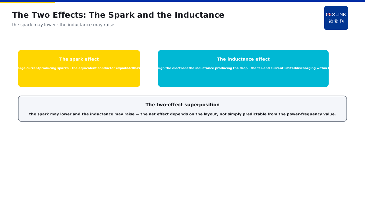
Direct Answer
The earthing resistance is measured at 4 Ω and qualified at ordinary times, but under the lightning current the earthing electrode seems to "become larger" — where does the problem lie? The answer: the power-frequency earthing resistance is a steady-state value measured with a small current slowly; the lightning current is a microsecond-level large current, and around the earthing electrode the soil has the spark effect and the inductance effect appears, so the impulse earthing resistance differs numerically from the power-frequency value; the effective utilization length of the long electrodes and the multiple radial electrodes is limited under the impulse, and the power-frequency value cannot be simply extrapolated.
At a workshop, the power-frequency earthing resistance was measured at 4 Ω and qualified, but after the thunderstorm season the equipment was still frequently damaged by strikes. The investigation found that the impulse earthing resistance under the lightning current far exceeded 4 Ω — the soil spark effect changed the current path, and the inductance effect of the long electrode made the far end not discharge effectively, so the earth potential rise exceeded the expectation. After the design was checked against the impulse earthing resistance and the electrode layout was optimized, the strike damage decreased obviously. The key distinction: the power-frequency value is the steady-state small-current value, and the impulse value is the instantaneous value under the lightning current — the spark effect and the inductance effect make the two differ; the effective utilization length of the long electrodes and the multiple radial electrodes is limited under the impulse, and the power-frequency value cannot be simply extrapolated.
Why:
- The power-frequency steady-state value: measured slowly with a small current;
- The impulse instantaneous value: under the microsecond-level large current;
- The spark effect: the soil discharge changes the current path;
- The inductance effect: the far end of the long electrode not effectively utilized.
Key insight: "The power-frequency value differs from the impulse value — the power-frequency value is the small-current steady-state value, while under the lightning current the spark effect changes the path and the inductance effect limits the far end, so the impulse value differs from the power-frequency value; the effective utilization length of the long electrodes and the multiple radial electrodes is limited, and the design must be corrected with the impulse coefficient."
At a substation, the power-frequency earthing grid resistance was qualified, but after one strike the secondary equipment was damaged; the review found that the impulse earthing resistance was far higher than the power-frequency value, and the earth potential rise exceeded the device withstand. After the design was corrected with the impulse coefficient, the same strike no longer damaged it. Lesson: the qualified power-frequency value does not mean the strike safety — the impulse value under the lightning current may be several times higher, and the design must be checked against the impulse earthing resistance.
Overview: run "how the power-frequency and the impulse current waveforms differ → how the spark effect and the inductance effect influence them → what the effective utilization length is → how the design corrects with the impulse coefficient" as one earthing-resistance cognition. The power-frequency earthing resistance is a steady-state value measured with a small current slowly; the lightning current is a microsecond-level large current, and around the earthing electrode the soil has the spark effect and the inductance effect appears, so the impulse earthing resistance differs numerically from the power-frequency value; the effective utilization length of the long electrodes and the multiple radial electrodes is limited under the impulse, and the power-frequency value cannot be simply extrapolated. The four layers are unfolded below.
A "water-pipe filling" analogy: think of the power-frequency measurement as slowly pouring water into the pool with a thin pipe to measure the water level — the flow small and the time long, and the water level reflects the "steady state"; the lightning current is like a fire-hose burst — the flow large and the time short, the water splashing around (the spark effect), and the water cannot reach the pool edge in time (the inductance effect limiting the far end). For the same pool (the electrode), the "water level" measured with the thin pipe (the power-frequency resistance) naturally differs from the "instantaneous water momentum" when the fire hose bursts (the impulse resistance). The effective utilization length is the "effective spraying distance of the hose": the water scatters if sprayed too far, and the far end of an over-long electrode does not discharge either. The water-pipe analogy: the power-frequency value = the thin-pipe slow pouring (the steady-state measurement), the lightning current = the fire-hose burst (the spark and inductance effects); the effective length = the effective spraying distance of the hose, and the over-long far end fails.
1. The Power-Frequency vs the Impulse: Where the Waveforms Differ
Step one: first look at the waveform difference between the power-frequency measurement and the lightning current.
The power-frequency measurement:
- The small current injected slowly;
- The frequency 50 Hz;
- The soil steady-state response;
- The steady-state resistance measured.
The lightning-current characteristics:
- The microsecond-level large current;
- The rich high-frequency components;
- The soil instantaneous response;
- Differing from the steady state.
The waveform-difference influence:
- The current large and the time short;
- The soil nonlinear response;
- The resistance not constant;
- The impulse value different.
Key insight: "The waveform difference sets the tone — the power-frequency value is the 50 Hz steady-state measurement with a small current, and the lightning current is the microsecond-level large current with many high-frequency components, with the soil responding instantaneously and nonlinearly, so the impulse value differs from the steady-state value."
2. The Two Effects: How the Spark and the Inductance Influence It
Step two: the influence of the spark effect and the inductance effect on the impulse earthing resistance.
The spark effect:
- The soil discharges under the large current;
- The soil breakdown produces sparks;
- The equivalent conductor expanded;
- The resistance decreased instead.
The inductance effect:
- The high-frequency current through the electrode;
- The inductance producing the voltage drop;
- The far-end current limited;
- Discharging within the effective length.
The two-effect superposition:
- The spark possibly lowering the resistance;
- The inductance possibly raising it;
- The net effect depending on the layout;
- Not simply predictable.
Key insight: "The two effects exist simultaneously — the spark effect expands the equivalent conductor by the soil discharge and may lower the resistance, and the inductance effect limits the far-end current by the high-frequency voltage drop and may raise it; the net effect depends on the layout, not simply predictable from the power-frequency value."
3. The Effective Utilization Length: What the Concept Is
Step three: the effective utilization length of the long electrodes and the multiple radial electrodes under the impulse.
The effective length:
- The current concentrated in the front section under the impulse;
- The far-end current very small;
- Only the front section discharging effectively;
- The long electrode not equal to the better.
The radial-electrode influence:
- The multiple radial electrodes in parallel;
- The insufficient spacing mutually shielding;
- The effective length of each limited;
- Not infinitely extended.
The design inspiration:
- The length not the longer, the better;
- The layout considering the spacing;
- Optimizing within the effective length;
- The impulse efficiency higher.
Key insight: "The effective length limits the discharge — under the impulse, the current is concentrated in the front section of the electrode and the far-end current is small, so the long electrode is not equal to the better; the radial electrodes with the insufficient spacing mutually shield, and the length and the spacing must be optimized within the effective length."
4. The Design Correction: How to Use the Impulse Coefficient
Step four: how to correct the power-frequency earthing resistance with the impulse coefficient in the design.
The impulse coefficient:
- The ratio of the impulse value to the power-frequency value;
- Reflecting the difference between the two values;
- Related to the soil and the length;
- The design correction parameter.
The correction method:
- The power-frequency value × the impulse coefficient;
- Estimating the impulse value;
- Comparing the earth-potential requirement;
- Judging whether qualified.
The optimization direction:
- Controlling the electrode length;
- The radial electrodes with the reasonable spacing;
- Lowering the impulse resistance;
- Verified with the online monitoring.
Key insight: "The correction uses the impulse coefficient — the power-frequency value × the impulse coefficient estimates the impulse value and compares the earth-potential requirement; optimize the electrode length and the radial-electrode spacing to lower the impulse resistance, and verify the actual performance with the online monitoring."
5. Product Implementation: Monitoring the Two States
WeiWuLian products bring the earthing-resistance monitoring to the two states:
- FR earthing-resistance monitor: the online monitoring of the power-frequency earthing resistance;
- The strike-event records: combined with the lightning-current records;
- The trend warning: identifying the earthing-performance changes;
- The data support: the basis for evaluating the impulse performance.
The design principle in one sentence: "The power-frequency value measurable and the impulse value estimable — the FR monitors the power-frequency earthing resistance online, and the strike records and the trend warning support the impulse-performance evaluation, with the design correction backed by the data."
6. Common Understanding Misjudgments
- "The qualified power-frequency value means the safety": wrong. The impulse value may be several times higher.
- "The longer the electrode, the better": wrong. The effective utilization length is limited, and the far end of the long electrode does not discharge.
- "The spark effect only lowers the resistance": wrong. The inductance effect may raise it, and the net effect depends on the layout.
- "The impulse value equals the power-frequency value": wrong. The two values are determined by the waveform and the effects, and the design must be corrected.
- "One measurement is enough": wrong. The earthing performance changes with the environment and must be continuously monitored.
Scope and Limitations
This article explains the difference between the power-frequency and the impulse earthing resistances (the waveform difference, the two effects, the effective length, and the impulse-coefficient correction), applicable to the lightning-protection earthing design and check. The specific values and the correction coefficients follow GB/T 50065-2011 and the design standards; this article explains only the concept logic. All cases are anonymized (a workshop/a substation) and do not refer to any specific customer.