 微物联研究院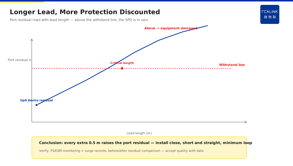
Direct Answer
The SPD is installed and the parameters are right — so why is nearby equipment still damaged by surges? The answer: surges are microsecond-scale high-frequency events, and the distributed inductance of the SPD's leads produces an extra voltage drop (L·di/dt) within that extremely short time. The longer the leads and the steeper the current rise, the higher the residual voltage added on top of the SPD's clamping voltage — this is the fundamental reason why an SPD must be installed close to the protected point, with short, straight leads forming the smallest possible loop.
An SPD in a distribution board was selected correctly per code, but it was mounted at the top of the cabinet while the protected variable-frequency drive was about 1.5 m away, with the routing looping halfway around the cabinet. After one thunderstorm the drive was damaged while the SPD itself stayed intact. Investigation: after the SPD clamped, the lead inductance produced an extra drop under the microsecond surge, and the combined residual at the drive's port far exceeded its withstand. After moving the SPD next to the drive and shortening/straightening the leads, no further damage. The key point: the SPD's clamping voltage is the "device residual"; the port residual the equipment actually sees is that plus the lead-inductance drop — the longer the lead, the more protection is discounted.
Why:
- Under a high-frequency surge the lead is not a wire: the microsecond di/dt is enormous, so distributed inductance creates a significant drop;
- L·di/dt adds up: lead residual = inductance × current rate of change; under a steep surge it can reach hundreds of volts;
- Longer leads mean higher residual: one extra metre can push the residual above the equipment's withstand;
- Installation principles: short, straight, small loop area, install close to the protected point.
Key insight: "The SPD's device residual + the lead-inductance drop = the real residual at the equipment port — the lead is part of the protection chain, not an arbitrary wire."
A factory once mounted the SPD at the main board while the equipment was in a sub-board, with about 3 m of lead coiled into loops; during the thunderstorm season the surge records at the equipment port showed high residual while the SPD showed no degradation. After relocating the SPD to the equipment cabinet and shortening/straightening the leads, the residual dropped markedly. Lesson: the lead between the SPD and the equipment is itself part of the surge protection — length and routing decide the protection effect.
1. Why the Lead Cannot Be Treated as a Wire Under High-Frequency Surges
Step one: how large is the microsecond current rate of change.
The "high-frequency" nature of surges:
- Lightning current rises in microseconds (very large di/dt);
- The equivalent frequency can reach several MHz (not the 50 Hz mains);
- Lead inductance that is negligible at 50 Hz becomes unignorable at MHz;
- Distributed inductance and capacitance both start to act.
The changing role of the lead:
- At mains frequency: the lead offers only small resistance;
- Under a surge: the lead inductance L dominates (reactance = ωL);
- Inductance "resists" current change → produces a voltage;
- The longer the lead, the larger the inductance (about 1 μH/m).
Why "right parameters are not enough":
- The SPD parameters (In/Up) describe only the device itself;
- The lead inductance outside the device is an "invisible extra residual";
- The actual port residual = device residual + lead drop;
- With poor lead routing, the SPD is installed in vain.
Key insight: "A surge is MHz-level high frequency — lead inductance goes from 'negligible' to 'dominant'; that is the physical root of lead problems."
2. L·di/dt: How the Lead Residual Is Calculated
Step two: one formula to understand the lead's influence.
The formula:
- Lead drop = L × di/dt;
- L: the loop inductance of the lead (henries);
- di/dt: the current rate of change (amperes per second);
- When the surge is steep, di/dt is huge → the drop is significant.
A sense of magnitude:
- Typical lead inductance: about 1 μH/m;
- Surge di/dt: can reach 10–100 A/μs (or higher);
- A 1 m lead drop: about 10–100 V (added to the residual);
- Long leads + steep surges → a drop of hundreds of volts.
Impact on equipment:
- Port residual = SPD clamping voltage + lead drop;
- The lead drop degrades the "effective protection level";
- Exceeding the equipment withstand → the equipment is damaged;
- This is why "the SPD is fine but the equipment failed".
Key insight: "L·di/dt shows the lead drop is proportional to length and to surge steepness — an inch more lead, a measure less protection."
3. Short, Straight Leads and Minimum Loop Area
Step three: how to wire on site.
Short leads:
- Place the SPD as close to the protected point as possible;
- Keep the total lead length short (including both SPD terminations);
- Each 0.5 m removed noticeably lowers the drop;
- Short leads also reduce the loop area.
Straight leads:
- No coiling, no detours (coiling adds inductance);
- Route straight, avoid "halfway around the cabinet" runs;
- Lay phase, neutral and protective earth conductors together side by side;
- Keep the spacing between conductors small (smaller loop area).
Minimum loop area:
- The surge-current path and the protected cable form a loop;
- The larger the loop area, the stronger the inductive coupling;
- Reducing the loop area reduces the induced residual;
- This is why "pair the conductors, route them close".
Key insight: "Short, straight, small loop — three wiring laws; every one reduces lead inductance and induced residual."
4. Close Installation vs Inter-Stage Distance
Step four: close does not mean the stages should be as near as possible.
Close installation:
- The final-stage SPD hugs the protected equipment (e.g., VFD, PLC supply side);
- The lead between the equipment and the SPD is shortest;
- This is the core requirement of "equipment-end protection";
- It does not conflict with the energy coordination of KD-0169.
Inter-stage distance:
- The Type-1 (entrance) and Type-2 (equipment end) need distance/decoupling;
- Inter-stage distance serves energy coordination (letting the upstream act first);
- Close installation is about the "final stage to equipment" segment;
- The two lead logics differ: distance between stages, shortest at the equipment end.
The relationship between the two:
- Type-1 SPD: at the entrance, discharges direct-strike energy;
- Type-2 SPD: at the equipment end, clamps with short leads;
- Inter-stage distance is set by energy coordination;
- The equipment-end lead is set by the "minimum loop".
Key insight: "Stages need 'distance' (energy coordination); the equipment end needs 'short' (close protection) — the design logics of the two lead segments must not be mixed."
5. Common Incorrect Routing Patterns on Site
Step five: which wiring habits to change.
Mistake 1: SPD at the top of the cabinet, equipment at the bottom:
- Leads of 1–2 m or more;
- Residual significantly raised. Correct: install close in the equipment cabinet.
Mistake 2: Coiled/detoured leads:
- Coiling adds inductance (effectively lengthens);
- Detours enlarge the loop area. Correct: short and straight.
Mistake 3: Phase and earth routed separately:
- The loop area grows, the induced residual rises;
- Correct: run them side by side, close together.
Mistake 4: The final SPD sharing a long lead with the equipment:
- The protection point moves downstream, the port residual exceeds the limit;
- Correct: connect the SPD at the closest point to the protected end.
Mistake 5: No verification after installation:
- The actual residual is unknown;
- Correct: verify with FS/ESM monitoring and surge records.
Key insight: "Check the five incorrect patterns — every one turns the 'device residual' into a 'port residual'; fixing the routing works better than buying a more expensive SPD."
6. Product Implementation: Intelligent Lightning-Protection Online Monitoring
WeiWuLian products make "lead quality" verifiable:
- FS/ESM SPD Monitor: monitors SPD state and leakage trends;
- Surge records: the actual residual/events at the equipment port can be replayed;
- Platform analysis: before/after residual comparison validates the routing retrofit;
- Construction acceptance: use monitoring data to accept the installation quality.
The design principle in one sentence: "Device selected right + leads wired right + monitoring verifies — only then does SPD protection truly land."
7. Common Misjudgments
- "Install it and forget it": not caring about the leads. Result: port residual exceeds the limit, equipment damaged. Correct: install close with short straight leads.
- Looking only at device parameters: ignoring lead inductance. Result: right parameters still let equipment be damaged. Correct: check the lead drop.
- Coiling/detouring leads: for convenience. Result: effectively longer inductance. Correct: short, straight, side by side.
- Confusing stage distance with the equipment end: lengthening the final-stage lead too. Result: the equipment-end residual exceeds the limit. Correct: keep the final stage close.
- No verification after installation: without monitoring. Result: the problem hides until damage. Correct: verify with FS/ESM monitoring and records.
Scope and Limitations
This article explains the physical mechanism of SPD lead loop inductance raising the residual (L·di/dt), the installation principles (short/straight/small loop), and the common incorrect routing patterns, applicable to SPD installation and construction acceptance. The quantitative relationship among lead length, loop area and residual depends on the surge waveform and site layout; follow GB 50343-2012 and related codes, completed by professional construction and commissioning. All cases are anonymized (a distribution board, a factory) and do not refer to any specific customer.