 微物联研究院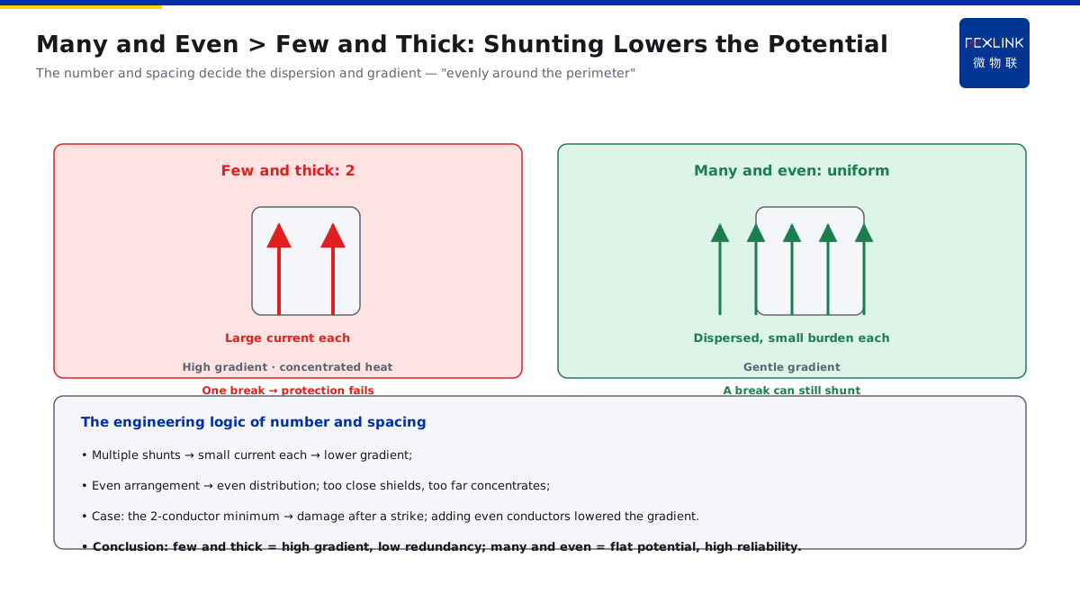
Direct Answer
Are the down-conductor sizes and numbers on the drawing picked by feel, or calculated from the lightning-current thermal effect and mechanical forces? The answer: the down-conductor cross-section is determined by the thermal effect of the lightning current (temperature rise not exceeding the limit) and by electromechanical forces; the number and spacing determine how the current disperses and how much the potential rises on each down-conductor — multiple evenly arranged conductors split the large current and lower the potential gradient of each one. That is why the standard requires down-conductors to be evenly arranged around the building perimeter, in no less than a certain number.
A project configured down-conductors at the "drawing minimum" — only two, with spacing far larger than the standard, and without using the building reinforcement as natural down-conductors. After a strike, equipment near the conductors was damaged. Review: after adding more down-conductors arranged evenly around the perimeter, the current dispersed, the potential gradient fell, and the problem did not recur. The key distinction: the down-conductor size and number are not "picked by feel" — the cross-section handles the thermal effect and mechanical force, and the number handles current dispersion and the potential gradient; each has its own basis.
Why:
- Cross-section: determined by the lightning-current thermal effect (temperature rise) and electromechanical force;
- Number: determines the current dispersion and the potential gradient;
- Even arrangement: multiple conductors split the current and lower each one's gradient;
- Safe distance: the clearance between down-conductors and protected objects has requirements.
Key insight: "The cross-section handles 'surviving the heat and force'; the number handles 'dispersing the current and flattening the potential' — both sizes and numbers have calculation bases, not guesses."
At a substation, building reinforcement was used as natural down-conductors, but the electrical continuity of the steel was not verified (poor laps), and a strike caused local sparking. After rectification — checking/welding the lap joints per the standard and forming a continuous electrical path — the problem disappeared. Lesson: natural down-conductors must meet electrical-continuity conditions — it is not "steel exists, so it works", but "continuous, capable of shunting, and with a flat potential".
1. How the Cross-Section Is Determined: Thermal Effect and Electromechanical Force
Step one: why numbers like φ10 round steel.
The thermal effect:
- The lightning current produces Joule heat in the down-conductor;
- The temperature rise relates to I²t (current squared × time);
- An insufficient cross-section → temperature rise over the limit → damage/melting;
- The cross-section must keep the temperature rise within the limit.
The electromechanical force:
- The lightning current produces electromagnetic force between conductors;
- At large currents the mechanical force is considerable;
- Insufficient cross-section/fixing → deformation/breakage;
- The electromechanical force determines the mechanical-strength requirement.
Materials and sizes:
- Round/flat steel per the standard minimum cross-section;
- Differences in conductivity/corrosion resistance;
- The size numbers come from the thermal + force double check;
- Stricter for high-rise/large-current scenarios.
Key insight: "The cross-section is set jointly by the thermal effect (temperature rise) and the electromechanical force — the size numbers are calculated, not copied from a drawing."
2. Number and Spacing: Current Dispersion and Potential Gradient
Step two: why "at least two, evenly arranged".
The role of the number:
- Multiple down-conductors shunt in parallel;
- The current in each one falls → less heating/lower potential;
- The current disperses into the ground at multiple points;
- More conductors → a smaller burden on each one.
The role of spacing:
- Even arrangement → even current distribution;
- Spacing too close → mutual shielding/uneven distribution;
- Spacing too large → local current concentration;
- Even distribution around the perimeter is key.
The potential gradient:
- A large current in a conductor → its own potential rises high;
- A large gradient → risk to nearby equipment/people;
- Multiple shunts → a smaller current each → lower gradient;
- That is why "many and even" beats "few and thick".
Key insight: "The number and spacing decide the current dispersion and the potential gradient — many conductors arranged evenly shunt the current and lower the potential, which is why the standard requires a certain number."
3. Why Many and Even Beats Few and Thick
Step three: the merits of the configuration.
The problems of few and thick:
- A large current in one conductor → a high potential gradient;
- Concentrated local heating;
- One break → the protection fails;
- Low redundancy.
The benefits of many and even:
- The current disperses; each conductor bears less;
- The potential gradient is gentle;
- A local break can still be shunted;
- High redundancy and reliability.
The engineering comparison:
- Two thick lines vs many even thin lines;
- The latter has a flatter potential and higher reliability;
- The standard takes "evenly around the perimeter, no less than a number";
- Balancing safety and cost.
Key insight: "Few and thick means a high gradient and low redundancy; many and even means a flat potential and high reliability — the standard choosing 'many and even' is no accident."
4. The Safe Distance between Down-Conductors and Protected Objects
Step four: why the distance matters.
Where the safe distance comes from:
- A down-conductor carrying current creates a strong surrounding field;
- Too close to a protected object → air/gap breakdown;
- Breakdown → side flash/counterattack (connecting to KD-0166);
- Insufficient distance is a counterattack channel.
How the distance is set:
- By the conductor current and potential level;
- By the breakdown characteristics in air/soil;
- The standard gives minimum clearance requirements;
- When it cannot be met, use equipotential measures.
Engineering practice:
- Route the conductors along exterior walls/independent columns;
- Keep clearances from protected equipment;
- Add protection/warnings in occupied areas;
- Use an equipotential network to remove potential differences.
Key insight: "A down-conductor carrying current has a high surrounding potential — keep the safe distance from protected objects, or air breakdown forms a counterattack; where the distance cannot be met, equipotential bonding makes up for it."
5. The Conditions for Using Building Reinforcement as Natural Down-Conductors
Step five: what using the reinforcement requires.
The basic conditions:
- Electrical continuity of the reinforcement (reliable laps);
- A continuous electrical path;
- A cross-section meeting the thermal/force requirements;
- Equivalence with artificial down-conductors.
Continuity verification:
- Are the laps/welds standard-compliant;
- Are the crossing points reliably connected;
- Electrical connection between ties and main bars;
- Verify by continuity testing (connecting to the FR product).
Notes:
- It is not "steel exists, so it works";
- The reinforcement in concrete must be continuous;
- Corrosion/breakage affects continuity;
- Recheck the continuity regularly.
Key insight: "The premise of a natural down-conductor is electrical continuity — reliable laps, a continuous path, capable of shunting, and rechecked by continuity tests regularly."
6. Product Implementation: Earthing and Continuity Monitoring
WeiWuLian products manage the down-conductor system with data:
- FR Earth-Resistance Monitor: online monitoring of the earthing-system state;
- Continuity recheck: continuity tests of down-conductors/equipotential bonds;
- Potential-risk assessment: flags abnormal potential gradients;
- Data loop: recheck the down-conductor state after lightning events.
The design principle in one sentence: "Size by thermal and force, number by shunting, continuity by testing — manage the down-conductor system with data."
7. Common Misjudgments
- "Copy the sizes from the drawing": not understanding the basis. Result: misconfigured for the scenario. Correct: recheck by the thermal/shunting logic.
- "Two thick lines are enough": ignoring the potential gradient. Result: high local potential. Correct: many, evenly arranged.
- "Spacing is arbitrary": ignoring the breakdown risk. Result: counterattack damage. Correct: keep the safe distance + equipotential bonding.
- "Steel exists, so it is a natural conductor": ignoring electrical continuity. Result: local sparking. Correct: verify continuity + test.
- "Done once installed": no continuity monitoring. Result: a break goes unnoticed. Correct: recheck continuity regularly.
Scope and Limitations
This article explains the parameter basis of down-conductors: the cross-section (thermal effect and electromechanical force), the number and spacing (shunting and the potential gradient), the safe distance, and the conditions for natural down-conductors, applicable to the design and understanding of down-conductor systems. The exact cross-section/number/spacing values follow GB 50057-2010 and its revisions; this article explains only the physics and engineering logic behind the parameters. All cases are anonymized (a project, a substation) and do not refer to any specific customer.