 微物联研究院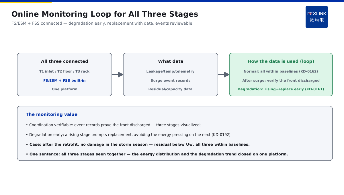
Direct Answer
From the utility inlet to the racks in a data center, how many SPD stages are needed, how big is each stage, and how do they coordinate? The answer: arrange three stages — a T1 at the main inlet (large discharge, diverting direct/induced energy), a T2 at the floor/distribution level (clamping the main residual), and a T3 in front of critical equipment (rack/UPS input, fine protection of the end). The three stages coordinate through lead distance and descending discharge capacity, bleeding the surge energy stage by stage and pushing the end residual voltage below the equipment Uw.
At a data center with only one SPD at the main inlet, rack equipment was still damaged in the storm season. After the three-stage retrofit (T1 discharging at the inlet, T2 clamping at the floor, T3 fine protection in front of the racks — with lead distance and descending capacity between stages), the measured end residual voltage dropped below the equipment withstand and no further damage occurred. The key distinction: three-stage configuration is not "installing more SPDs" but a position—capacity—distance trinity of energy coordination — T1 discharges, T2 clamps, T3 protects the end; the residual pushed below Uw means it is configured right.
Because:
- The T1 role: discharging direct/induced energy at the inlet (large capacity);
- The T2 role: clamping the main residual (medium capacity);
- The T3 role: fine protection of the end equipment (small capacity);
- The coordination core: stage distance + descending capacity = energy bled stage by stage.
Key insight: "Three stages coordinate through position—capacity—distance — T1 discharges, T2 clamps, T3 protects the end; the residual pushed below Uw means it is right."
At a data center after the three-stage configuration, the measured rack-front residual was below the equipment Uw and no damage occurred in the storm season. Lesson: one stage cannot protect the end — three stages bleed the energy stage by stage and only then the end residual holds.
Overview: split "discharge—clamp—protect" into three positions. The whole power path is an energy channel: surge enters from the utility inlet and must decay stage by stage. T1 discharges the largest direct/induced energy at the inlet; T2 bleeds another layer at the floor/distribution and clamps the residual to a medium level; T3 bleeds the last layer at the equipment entrance and pushes the residual below the equipment Uw. Each stage has one role; together they complete "energy bled stage by stage, residual pushed down stage by stage". The five steps below expand: positions and roles, capacity and waveform selection, stage distance and energy coordination, T3 fine protection of the end, and bringing all three stages into online monitoring.
1. The Positions of the Three Stages and Each Role
Step one: where each stage goes and what it does.
T1 (main inlet cabinet):
- At the utility inlet/main distribution cabinet;
- Discharges direct-strike/large induced energy;
- Large capacity (e.g. 50kA, 10/350μs);
- The first energy gate.
T2 (floor/distribution):
- At the floor/distribution cabinet;
- Clamps the main residual;
- Medium capacity (e.g. 20kA, 8/20μs);
- The middle stage connecting above and below.
T3 (rack/UPS input):
- At the rack input/UPS input;
- Fine protection of the end equipment;
- Small capacity, low residual (e.g. 10kA, 8/20μs);
- The last-centimeter protection.
The division of roles:
- T1 discharges the large energy;
- T2 clamps the residual;
- T3 protects the end;
- Each stage has its own role.
Why three stages, not two: the two-stage configuration (T1+T2 only) leaves a gap between the floor and the racks — after the T2 residual rises again through the leads, it may still exceed Uw at the precision equipment entrance. The extra T3 puts the last clamp at the equipment entrance, and only then is the end residual truly pushed down. Conversely, T1 only or T3 only both fail: T1 only leaves the end residual too high; T3 only gets destroyed by the large energy. Position decides the role, and the role decides the number — three stages are not "more is better" but each stage exactly carries one energy layer.
Key insight: "Each stage has its own role: T1 discharges at the inlet, T2 clamps at the floor, T3 protects the racks — the position decides the role."
2. Capacity and Waveform Selection for T1/T2/T3
Step two: how big each stage should be.
T1 selection:
- Per the building lightning-current energy;
- The 10/350μs waveform (direct-strike simulation);
- Capacity per the LPZ0-LPZ1 boundary (relating to KD-0165);
- Large capacity is the first requirement for T1.
T2 selection:
- The 8/20μs waveform (induced simulation);
- Capacity per the LPZ1-LPZ2 boundary;
- Low residual;
- Clamping performance is the key for T2.
T3 selection:
- Matching the end equipment Uw;
- Low residual (Up < Uw);
- Fast response;
- Fine protection is the core of T3.
The coordination principle:
- Capacity descending stage by stage;
- Residual descending stage by stage;
- Waveform per the boundary;
- Do not skip a stage (missing T1 or T3).
The role of Uc/In/Imax in selection: four key parameters must be seen together. Uc (max continuous operating voltage) must exceed the highest sustained system voltage, or the SPD destroys itself under the grid voltage first; In (nominal discharge current) is the basis of coordination — the stages are designed with In descending; Imax (max discharge current) decides the large-energy capability, and T1's Imax is usually much larger than T2/T3; Up (voltage protection level) directly decides the end safety — T3's Up must be below the equipment Uw. The selection order: first set the waveform and capacity per the boundary (10/350μs for T1, 8/20μs for T2/T3), then set Uc per the system voltage, finally set T3's Up per the equipment Uw. Parameters are not "bigger is better" — each stage exactly meets its role: T1 resists large energy, T2 clamps, T3 protects the end.
Key insight: "Select the capacity per the boundary: T1 large capacity at 10/350μs, T2 clamping at 8/20μs, T3 low residual matched to Uw — capacity descending, residual descending, no skipped stage."
3. Stage Distance and Energy Coordination
Step three: how the stages coordinate.
Distance coordination:
- Keep the lead distance between stages (e.g. ≥10m);
- The distance lets the SPDs act in sequence;
- Insufficient distance → coordination fails;
- The lead length also affects the residual (relating to KD-0172).
Energy distribution:
- T1 bleeds most of the energy;
- T2 bleeds the remaining main part;
- T3 bleeds the last part and clamps;
- Stage by stage, decaying stage by stage.
The signs of failed coordination:
- All the energy presses onto one stage;
- That stage is repeatedly damaged;
- The end residual stays high;
- Check the stage distance and the capacity.
Practice:
- Insufficient distance → add a decoupler or adjust the position;
- Mismatched capacity → adjust the selection;
- Verify the energy distribution with data;
- Three stages working together means it is configured right.
The decoupling scheme when the distance is short: in reality, limited by the machine-room space, the leads between T1-T2 and T2-T3 often cannot stretch 10 meters. Two measures: first, add a decoupler (decoupling inductor) — the inductive impedance staggers the energy in time, letting the front stage act and discharge first and the rear stage clamp after — the decoupler selection must match the capacity; second, adjust the installation position, putting each SPD as close as possible to its protected cabinet and shortening the leads (overlong leads raise the residual themselves, relating to KD-0172). The hard indicator of working coordination: after a surge event, the front stage carries most of the discharge, the rear stage is not repeatedly damaged, and the measured end residual is below Uw. Coordination is not paper distance but verified with event data — short distance, add a decoupler; leads as short as possible; the rear stage not repeatedly damaged means it is right.
Key insight: "Coordinate through distance and descending capacity — the distance lets the SPDs act in sequence and the energy bleeds stage by stage; short distance, add a decoupler; mismatched capacity, adjust the selection."
4. T3 Fine Protection of the End Precision Equipment
Step four: the last centimeter.
Why T3 is needed:
- The T1/T2 residual may still exceed the precision equipment Uw;
- The rack/UPS front is close to the end;
- The residual surge still threatens the equipment;
- T3 pushes the residual to the final low point.
T3 configuration points:
- At the rack input distribution;
- At the UPS input/output;
- Low residual, fast response;
- Up strictly below Uw.
Precision equipment protection:
- Servers/storage/network devices;
- Signal ports also get SPDs (the signal path);
- Power + signal dual protection;
- The end is the key coverage.
Verification:
- Measure the rack-front residual;
- Compare with the equipment Uw;
- Residual < Uw means it is in place;
- Record the data in a loop.
The UPS and rack-entry details: the UPS and the rack power entry are the two key T3 landing points. A T3 at the UPS input stops surges from the power side hitting the internal power devices; consider another stage at the UPS output, because the inverter itself also generates switching transients. The rack power entry (PDU input) is the last centimeter — here Up must be strictly below the Uw of the in-rack equipment (servers/storage/network usually have a low Uw). Both inputs of dual-power equipment must be covered; important signal ports (network, storage links) are configured separately with signal SPDs. The T3 landing points must be "pressed against the equipment" — UPS input/output and PDU entry dual coverage, power + signal dual protection, Up strictly below Uw.
Key insight: "T3 pushes the residual to the final low point — low-residual SPDs at the rack/UPS front, Up strictly below Uw, power + signal dual protection, verified by measurement."
5. Bringing All Three SPD Stages into Online Monitoring
Step five: how to manage them.
What to monitor:
- The state of each stage (leakage/temperature/telemetry);
- Surge event records;
- Residual/capacity data;
- The state visible online.
What to use:
- The FS/ESM SPD monitor;
- The FSS intelligent surge protective device with built-in monitoring;
- All three stages connected uniformly;
- The data on the platform.
The monitoring value:
- Degradation found early (relating to KD-0161);
- Replacement with data (relating to KD-0192);
- Surge events reviewable;
- Three-stage coordination visualized.
Closed-loop management:
- Abnormal state → replacement prompt;
- Event records → attribution review;
- Data loop → continuous improvement;
- Three-stage protection always online.
Monitoring points and data access: the monitoring of the three stages must be "all three seen, one platform". The placement principle: T1 at the main inlet, T2 at the floor/distribution, T3 at the rack/UPS front — each stage gets an FS/ESM monitor (or the FSS built-in), and the leakage/temperature/telemetry of all three stages connect to one lightning-protection platform. How to read the data: normally the leakage/temperature of all three stages stay within their baselines (relating to KD-0162); after a surge, look at the event record to judge whether the energy was mainly discharged by the front stage as expected (verifying the coordination); if a stage's leakage/temperature keeps rising, that stage is degrading (relating to KD-0161) — prompt the replacement early so the energy is not pressed onto the next stage after failure (relating to KD-0192). The final value of monitoring is making the coordination verifiable and the degradation early — all three stages seen together, the energy distribution and the degradation trend closed on one platform.
Key insight: "Bring all three stages into online monitoring — leakage/temperature/telemetry connected uniformly; degradation found early, replacement with data, events reviewable."
6. Product Implementation: Three-Stage Configuration and Monitoring as One
WeiWuLian products manage the data-center three-stage SPD:
- FSS Intelligent Surge Protective Device: T1/T2/T3 stage products with built-in monitoring;
- FS/ESM SPD Monitor: three-stage state/leakage/telemetry online;
- Energy coordination: descending capacity + stage-distance design;
- Closed-loop monitoring: degradation warning + event review.
The design principle in one sentence: "T1 discharges, T2 clamps, T3 protects the end — three-stage energy coordination + online state monitoring; residual pushed below Uw, degradation found early."
7. Common Configuration Misjudgments
- "Only one stage at the main inlet": ignoring the end. Result: the end equipment still threatened. Correct: three stages.
- "Installing more SPDs is enough": ignoring the coordination. Result: energy presses onto one stage. Correct: position—capacity—distance coordination.
- "The stage distance is arbitrary": ignoring the sequencing. Result: coordination fails. Correct: keep the lead distance between stages.
- "Only the capacity, not the residual": ignoring the end Uw. Result: the end still exceeds its withstand. Correct: residual < Uw.
- "Installed and forgotten": ignoring the monitoring. Result: degradation unknown. Correct: all three stages into online monitoring.
Scope and Limitations
This article gives the three-stage SPD (T1/T2/T3) configuration scheme for data-center power (position roles, capacity and waveform selection, stage distance and energy coordination, end T3 fine protection, online monitoring), applicable to the design and optimization of data-center SPD systems. The exact parameters and requirements follow GB 50343-2012, IEC 61643-11 and the manufacturers' data; this article explains only the configuration logic and coordination points. All cases are anonymized (a data center) and do not refer to any specific customer.