 微物联研究院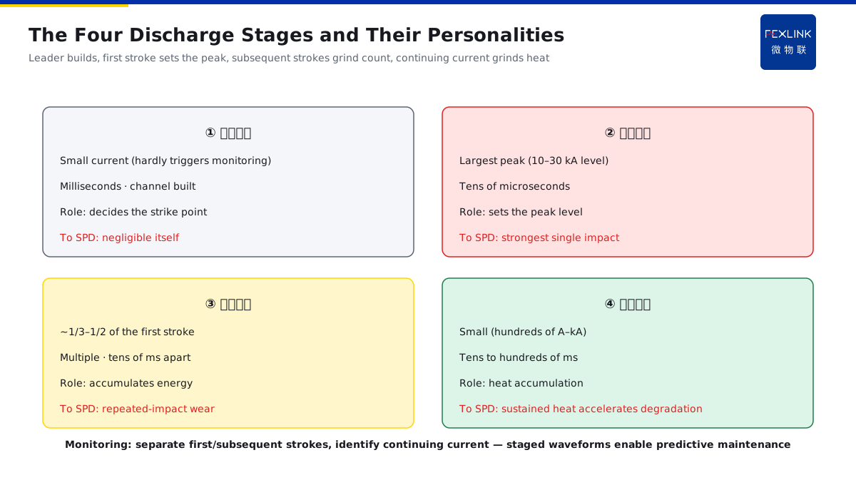
Direct Answer
Why does one "lightning strike" appear as a string of pulses in the monitoring waveform instead of a single "bang"? The answer: the full course of one cloud-to-ground flash consists of the downward leader (building the channel), the first return stroke (largest amplitude, concentrated energy), multiple subsequent return strokes, and possibly a continuing current (small amplitude but long duration) — what the monitor records as "one strike" is actually a superposition of several discharge stages, which is why an SPD can be progressively degraded by repeated impacts.
At a substation, the FL Lightning-Current Monitor recorded one ground flash: first a large 28 kA pulse (first return stroke), then three 3–8 kA pulses within 200 ms (subsequent return strokes), and finally a low-amplitude current lasting tens of milliseconds (continuing current). If one only reads "strike count = 1", the cumulative stress on the SPD across this chain of impacts is missed. The key point: the first return stroke sets the "peak level"; the subsequent strokes and continuing current set the "cumulative energy" — SPD degradation is often driven not by the single big pulse but by the accumulated multiple impacts.
Why:
- Downward leader: the stepped leader extends toward the ground, establishing the discharge channel (stage one);
- First return stroke: the first large current surge once the channel is bridged — largest amplitude, concentrated energy (stage two);
- Subsequent strokes: the channel can re-ionize, producing several smaller return strokes (stage three);
- Continuing current: finally, a low-amplitude, long-duration current whose heat accumulation is not negligible (stage four).
Key insight: "One ground flash = leader + first return stroke + subsequent strokes + continuing current — 'strike count' is not 'one stress event'."
At a factory, an SPD failed after "1 strike" was counted in one thunderstorm. Reviewing the waveform: it was actually 1 first return stroke + 4 subsequent strokes + a continuing current — the SPD suffered repeated impacts before degrading to failure. Lesson: do not judge lightning by count alone; look at the staged waveform — cumulative stress is the real enemy of SPDs.
1. Downward Leader: Building the Lightning Channel
Step one: a strike begins with an "invisible channel".
The nature of the leader:
- After charge accumulates in the cloud, the channel extends downward in stepped leaders;
- The leader carries little current, "paving the way" for the large current to follow;
- Leader direction is influenced by the electric field and terrain, and it may branch;
- Channel establishment takes milliseconds (much longer than the return stroke).
Why it matters:
- The leader decides "where the lightning hits" (the strike point);
- Branching leaders create multiple strike points;
- The leader current is small and often does not trigger monitoring;
- But the leader channel is the "carrier" of the later return stroke.
Meaning for monitoring:
- The small leader current is usually not recorded as a "strike";
- But strike-point determination relies on leader-channel analysis;
- The leader stage sets the "starting point" the down-conductor/air-termination receives;
- Understanding the leader explains "why lightning hits here and not there".
Key insight: "The leader is the 'pathfinder' of the channel — small current, big influence; it decides where the strike lands."
2. First Return Stroke: The Largest Short Pulse
Step two: the "main event" of the strike.
The nature of the return stroke:
- When the leader channel is bridged, ground charge surges upward along the channel;
- The first return stroke has the largest amplitude (typically 10–30 kA, sometimes more);
- Duration is short (tens of microseconds);
- Energy is concentrated near the peak.
Why it is "most visible":
- The largest pulse in the monitoring waveform is usually the first return stroke;
- The peak drives the Iimp selection for SPDs;
- The concentrated energy hits equipment hardest;
- The steep waveform (large di/dt) gives strong induction effects.
Engineering significance:
- Peak and waveform are used to assess SPD discharge requirements;
- The energy of the first stroke directly affects SPD lifetime;
- Strike counting often keys on the first return stroke;
- But looking only at the first stroke underestimates cumulative damage.
Key insight: "The first return stroke is the 'peak event' — big and short, it drives selection; but it is not the whole stress picture."
3. Subsequent Strokes and Continuing Current: Small but Grinding
Step three: why the strike "is not over".
Subsequent strokes:
- The channel can re-ionize, producing multiple return strokes;
- Amplitude is smaller than the first (typically 1/3–1/2 of it);
- Intervals are tens of milliseconds;
- Multiple strokes add up to significant cumulative energy.
Continuing current:
- Finally, a low-amplitude current may last tens to hundreds of milliseconds;
- Small amplitude (hundreds of amperes to a few kiloamperes);
- Long duration makes heat accumulation (Joule heating) significant;
- It is an important source of heating in down-conductors and connections.
Meaning for SPDs:
- Multiple impacts consume SPD lifetime with every discharge;
- Continuing current accelerates degradation through heat;
- Monitoring must record "staged waveforms", not just a count;
- Degradation often appears as "sudden failure after many small impacts".
Key insight: "Subsequent strokes and continuing current are 'cumulative events' — small and long, the main force that grinds down SPDs."
4. What Multi-Stage Discharge Means for Cumulative SPD Damage
Step four: connecting the waveform to SPD lifetime.
Cumulative damage mechanism:
- Every discharge imposes electrical and thermal stress on the SPD;
- Multiple strokes mean multiple impacts (not one);
- Continuing current means sustained heat input;
- Once the accumulation reaches a critical point → thermal disconnection/failure.
What monitoring must provide:
- Record the peak and timing of every stroke;
- Distinguish the first stroke from subsequent strokes;
- Identify the continuing-current segment (duration/charge);
- Correlate SPD state (leakage/temperature) changes.
Why "count is not enough":
- A count of 1 is not a stress of 1;
- The same count can hide very different waveforms and damage;
- Count-only monitoring cannot warn of progressive degradation;
- Staged waveforms are needed for predictive maintenance.
Key insight: "The SPD's enemy is 'cumulative stress' — monitoring must record staged waveforms to support predictive maintenance."
5. Why "Strike Count" Is Not "One Damage Event"
Step five: the real relationship between count and stress.
Count vs stress:
- One ground flash may contain 1 first stroke plus several subsequent strokes;
- The counter records "1", but the SPD may suffer 4–5 impacts;
- The long-term heat input of the continuing current is not in the count;
- Stress = frequency × amplitude × duration (combined).
Engineering conclusions:
- Strike statistics serve environmental assessment (related to N/Ng);
- SPD lifetime assessment needs cumulative stress (waveform);
- The monitoring platform should provide waveform playback;
- Degradation warnings combine leakage and strike history.
Product implementation:
- FL Lightning-Current Monitor records staged waveforms;
- The platform splits statistics by "first stroke/subsequent strokes/continuing current";
- Correlate with SPD state (FSS/leakage monitoring);
- Achieve "assess SPD remaining life after a strike".
Key insight: "Count serves environmental assessment; waveform serves lifetime judgment — record both to understand lightning."
6. Common Misjudgments
- Treating a strike as a single "bang": looking only at the count. Result: cumulative stress underestimated. Correct: read the staged waveform.
- Watching only the first-stroke peak: ignoring subsequent strokes. Result: energy accumulation underestimated. Correct: count all strokes and the continuing current.
- Blaming "lightning too strong" when the SPD fails: not checking the waveform. Result: the real cause (multiple-impact accumulation) is hidden. Correct: replay the strike waveform and correlate with SPD failure.
- Dismissing the continuing current: thinking a small current is harmless. Result: heat-accumulation degradation ignored. Correct: watch long, low-amplitude current segments.
- Disconnecting count from lifetime: counting strikes without correlating equipment. Result: no predictive maintenance. Correct: correlate waveforms with device state.
Scope and Limitations
This article describes the four stages of one cloud-to-ground flash (downward leader, first return stroke, subsequent strokes, continuing current) and their meaning for cumulative SPD damage, applicable to lightning-current waveform interpretation and lightning-protection equipment lifetime assessment. The quantitative characteristics of ground flashes (typical amplitude, duration, charge) vary strike by strike; specific engineering parameters need site monitoring data and the GB/T 21714 series. All cases are anonymized (a substation, a factory) and do not refer to any specific customer.