 微物联研究院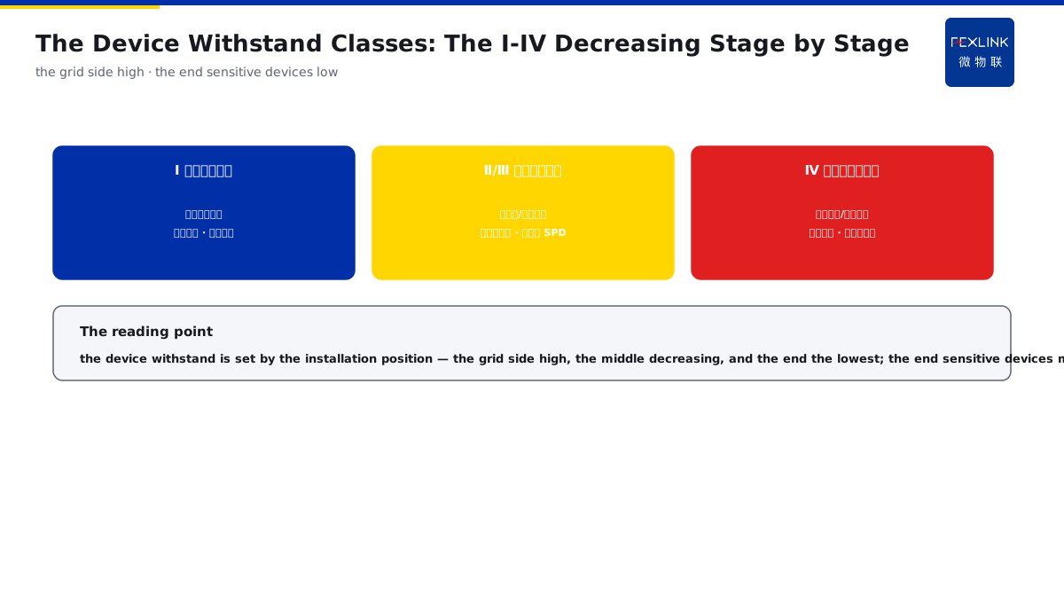
Direct Answer
Having selected an SPD with Up = 1.5 kV, is the protected device really safe? The answer: the criterion of the protection coordination is that Up (the residual voltage after the SPD limiting) should be lower than the rated impulse-withstand voltage Uw of the protected device with a margin; the devices are divided into the I-IV withstand classes by the installation position (decreasing step by step from the grid side to the sensitive-device end), and the closer to the device end, the more the fine-protection SPD with the lower Up should be used; the typical manifestation of the coordination failure is that the SPD is intact while the device is still damaged.
At a workshop, the distribution cabinet was equipped with an SPD; after the strike, the SPD was intact but the UPS burned. The investigation found that the SPD had Up = 1.5 kV, while the UPS, as the end sensitive device, had Uw = only 1.0 kV — Up was higher than Uw, the residual voltage exceeded the device withstand, and the device was broken down. After replacing it with the end fine-protection SPD with a lower Up, the same strike no longer damaged it. The key distinction: the SPD being intact does not mean the protection succeeded — the criterion is Up < Uw with a margin; the devices are divided into the I-IV withstand classes by the installation position, the grid side with a high withstand and the end sensitive devices with a low withstand, and the closer to the end, the more the SPD with the lower Up should be used.
Why:
- Up is the residual voltage: the voltage after the SPD limiting;
- Uw is the withstand: the impulse voltage the device can bear;
- The coordination criterion: Up should be lower than Uw with a margin;
- The end fine protection: the SPD with the lower Up at the device end.
Key insight: "The coordination criterion is Up < Uw — the residual voltage after the SPD limiting is lower than the device withstand with a margin; the devices are divided into the I-IV withstand classes decreasing step by step, the end sensitive devices with a low Uw, and the fine-protection SPD with the lower Up should be used at the end."
At a commercial building, the end network devices were frequently damaged while all the SPDs were intact. The review found that only one stage of the coarse-protection SPD (with a high Up) was used at the end, and the residual voltage still exceeded the network-device withstand. After adding the fine-protection SPD (with a low Up) at the device front, the damage disappeared. Lesson: one-stage SPD is not enough — the residual voltage decreases stage by stage and the end fine protection completes it; the Up-Uw coordination is complete only then.
Overview: run "how the Up-Uw coordination chain decreases → how to read the I-IV withstand classes of the devices → how the line length and the decoupling affect the end residual voltage → how to review the coordination failure" as one protection-coordination cognition. The criterion of the protection coordination is that Up (the residual voltage after the SPD limiting) should be lower than the rated impulse-withstand voltage Uw of the protected device with a margin; the devices are divided into the I-IV withstand classes by the installation position (decreasing step by step from the grid side to the sensitive-device end), and the closer to the device end, the more the fine-protection SPD with the lower Up should be used. The four layers are unfolded below.
A "three-stage dam" analogy: think of the protection coordination as three-stage dams arranged along the river. The upstream main dam (T1) discharges most of the flood peak (the lightning current), the midstream auxiliary dam (T2) further trims the peak, and the downstream final dam (T3) presses the passing water to the lowest — the "discharged water level" (Up) of each dam must be lower than the height of the downstream bank (Uw), otherwise the flood still overflows the bank (the device is broken down). The I-IV withstand classes are the "bank heights": the upstream bank high and the downstream bank low, and the closer to the end, the lower the bank and the more the final dam must press the water level down. The dam analogy: T1/T2/T3 = the three-stage dams trimming the peak stage by stage, Up = the discharged water level and Uw = the bank height — the water level must be lower than the bank, and the lower the end bank, the more the water level must be pressed down.
1. The Up-Uw Coordination Chain: How It Decreases
Step one: first look at how Up decreases stage by stage from the main distribution to the end device.
The T1 coarse protection:
- Installed at the main incoming line;
- Discharging most of the lightning current;
- The Up relatively high;
- Responsible for "discharging the main strike current".
The T2 protection:
- Installed at the sub-distribution;
- Further limiting the residual voltage;
- The Up lower than T1;
- Responsible for "pressing the residual voltage".
The T3 fine protection:
- Installed at the front of the sensitive device;
- The Up the lowest;
- Close to the device;
- Responsible for "the final limiting".
Key insight: "The coordination chain decreases stage by stage — T1 discharges the main strike current (high Up) → T2 presses the residual voltage (medium Up) → T3 limits close to the device (the lowest Up); the Up of each stage should be lower than the Uw of the next-stage device."
2. The Device Withstand Classes: How to Read the I-IV Classes
Step two: the devices are divided into the I-IV withstand classes by the installation position.
The I class (the grid side):
- The main distribution cabinet equipment;
- The highest withstand;
- Bearing large energy;
- The coarse protection sufficient.
The II/III classes (the middle layers):
- The sub-distribution/branch equipment;
- The withstand decreasing stage by stage;
- Coordinated with the medium SPDs;
- The residual-voltage requirement higher.
The IV class (the end sensitive):
- The electronic equipment/precision instruments;
- The lowest withstand;
- The fine protection needed;
- Up must be very low.
Key insight: "The I-IV withstand classes decrease stage by stage — the grid side with the highest withstand (the coarse protection sufficient), the middle layers decreasing stage by stage (coordinated with the medium SPDs), and the end sensitive devices with the lowest withstand (the fine protection must be used, with Up very low)."
3. The Line Length and the Decoupling: How They Affect the End Residual Voltage
Step three: the influence of the line length and the decoupling on the end residual voltage.
The line-length influence:
- The distance from the SPD to the device;
- The longer the line, the larger the induction;
- The end residual voltage rising;
- The shorter the distance, the better.
The decoupling influence:
- The decoupling between the SPD stages;
- Ensuring the stage-by-stage coordination;
- The residual voltage superposed without the decoupling;
- The device bearing higher.
The installation points:
- The SPD close to the device;
- The leads short and straight;
- The decoupling meeting the requirement;
- The residual voltage actually lower.
Key insight: "The line length and the decoupling affect the end residual voltage — the longer the line from the SPD to the device, the higher the induced residual voltage, and the residual voltage is superposed without the decoupling; with the SPD close to the device, the leads short and straight, and the decoupling qualified, the end residual voltage is really lower."
4. The Coordination-Failure Review: The SPD Intact, the Device Damaged
Step four: the typical review of the coordination failure (the SPD intact, the device damaged).
The typical phenomenon:
- The SPD intact;
- The device damaged;
- Misjudged as the SPD failure;
- Actually the coordination failure.
The review path:
- Check the Up of the SPD;
- Check the Uw of the device;
- Compare the coordination criterion;
- Find the residual-voltage over-limit point.
The rectification measures:
- Adding the fine protection at the end;
- Shortening the SPD-device distance;
- Checking the decoupling configuration;
- Re-coordinating Up and Uw.
Key insight: "The coordination-failure review — the SPD intact and the device damaged is not the SPD failure but Up exceeding Uw; check Up, check Uw, compare the criterion to find the residual-voltage over-limit point, add the fine protection at the end, shorten the distance, check the decoupling, and re-coordinate."
5. Product Implementation: The Coordination Verifiable
WeiWuLian products bring the protection coordination to the verifiable level:
- FSS intelligent surge protective device: the staged coordination, with Up verifiable;
- The monitoring alarm: the SPD degradation and the operation records;
- The strike review: the operation data compared with the device damage;
- The loop improvement: the coordination scheme continuously optimized.
The design principle in one sentence: "The coordination calculated clearly and the monitoring follows up — the FSS staged coordination with Up verifiable, the operation and damage data compared in the review, and the coordination scheme continuously optimized, so that the SPD intact and the device safe."
6. Common Understanding Misjudgments
- "The SPD intact means the protection succeeded": wrong. The device still burns when Up exceeds Uw.
- "The smaller the Up, the better, regardless of the position": wrong. The stages are coordinated by the position, and only the end needs the lowest Up.
- "The device withstands are the same": wrong. The I-IV classes decrease stage by stage, with the end the lowest.
- "The line length does not matter": wrong. The longer the line, the higher the end residual voltage.
- "One-stage SPD does everything": wrong. The coarse protection plus the fine protection coordinated stage by stage is complete.
Scope and Limitations
This article explains the Up-Uw protection coordination (the coordination chain, the device withstand classes, the line length and the decoupling, and the coordination-failure review), applicable to the SPD selection and the coordination judgment. The specific values follow IEC 61643-11, GB/T 18802.11 and the device manuals; this article explains only the coordination logic. All cases are anonymized (a workshop/a commercial building) and do not refer to any specific customer.