 微物联研究院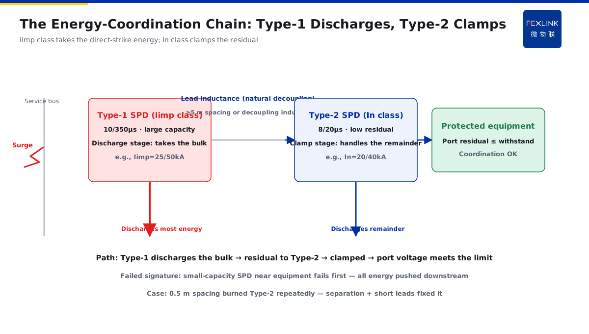
Direct Answer
When several SPDs are installed in stages along the distribution, who discharges first and who takes how much energy when a surge arrives? The answer: multi-stage SPDs form a natural coordination through lead inductance and their respective voltage protection levels — the upstream stage (near the service entrance, with large discharge capacity) discharges most of the energy first and reduces the residual voltage to what the downstream stage can withstand; the downstream stage handles only the remainder. The typical signature of failed coordination is that the small-capacity SPD near the equipment fails first, meaning all the energy was pushed onto the downstream stage.
A distribution room installed two stages: a Type-1 SPD at the main board (Iimp 25 kA, 10/350 μs) plus a Type-2 SPD at the equipment end (In 20 kA, 8/20 μs). After a thunderstorm season, inspection found the Type-1 intact and the Type-2 burnt out. The investigation showed the two stages were only 0.5 m apart with long leads, so no energy coordination was established — the surge reached the downstream stage before the upstream could fully discharge, and the small-capacity Type-2 could not take it. After increasing the separation (per code ≥ 5 m or adding a decoupling inductor) and shortening the leads, coordination was restored. The key point: energy coordination decides "who acts first and who takes how much" — upstream takes the bulk, downstream backs it up; failed coordination means the downstream fails first.
Why:
- Upstream discharges first: the Type-1 SPD near the service entrance has large discharge capacity (Iimp class) and releases most of the lightning current;
- Downstream handles the remainder: the Type-2 SPD (In class) clamps the residual further to protect the equipment port;
- Lead inductance acts: the inter-stage distance/lead inductance makes the upstream operate first and "holds" the impact energy at the line side;
- Failed-coordination signature: the small-capacity SPD near the equipment fails first, meaning coordination was never established.
Key insight: "Energy coordination means upstream acts first and downstream backs it up — achieved by staged discharge capacity plus lead inductance, not by simply stacking SPDs."
A factory once installed three SPDs within 3 metres "to be safer", only to have the one nearest the equipment fail repeatedly, again and again after replacement. After reconfiguring by energy coordination (Type-1 Iimp + Type-2 In + proper separation), the damage stopped. Lesson: more SPDs is not safer — mis-coordinated stages make the downstream fail first; coordination matters more than quantity.
1. What Energy Coordination Solves: Who Discharges, Who Clamps
Step one: why coordination is needed.
The essence of the problem:
- Every SPD stage must share the surge discharge;
- Without coordination, the energy can concentrate on one stage;
- A small-capacity downstream stage takes large energy → fails first;
- The equipment end loses protection (a failed SPD exposes the port).
Coordination goals:
- The upstream (Type-1) discharges most of the energy;
- The residual voltage stays within the equipment withstand;
- The downstream only handles the "remainder";
- All stages age evenly; none fails prematurely.
Two roles:
- Discharge stage: near the service entrance, large capacity (Iimp class, 10/350 μs);
- Clamp stage: near the equipment, low residual voltage (In class, 8/20 μs);
- Optional intermediate stage: a compromise of capacity and residual voltage;
- Roles are set by discharge capacity and installation position.
Key insight: "Coordination solves 'who acts first, who backs up' — Type-1 discharges, Type-2 clamps; only then the downstream does not fail first."
2. How Lead Inductance Works in Inter-Stage Coordination
Step two: how the stages "naturally coordinate".
Lead inductance:
- The wiring between an SPD and the bus has inductance;
- Surge current changes fast (large di/dt), producing a voltage drop across the inductance;
- That voltage drop makes the upstream SPD experience the voltage first and conduct first;
- Shorter and straighter leads mean less inductance (clearer coordination).
Natural coordination mechanism:
- When the surge arrives, the Type-1 SPD operates first due to the inductance voltage drop;
- Type-1 discharges most of the current and the residual drops;
- Type-2 sees an already-reduced surge;
- With sufficient inter-stage distance, Type-2 never operates before Type-1.
Engineering points:
- Keep the Type-1-to-Type-2 distance per code (generally ≥ 5 m or per calculation);
- When the distance is insufficient, add a decoupling inductor (to emulate inductance);
- Keep leads short, straight, and avoid coiling;
- Include the lead length in the coordination calculation.
Key insight: "Lead inductance is the 'natural decoupler' — Type-1 acts first, Type-2 second; when the distance is short, add a decoupling inductor."
3. The Division of Labour Between Iimp and In
Step three: what the two parameters govern.
Iimp (Type-1, 10/350 μs):
- Direct-strike waveform (the strong impact of direct/induction strikes);
- Large discharge capacity (kA level, e.g., 12.5/25/50);
- Installed at the main distribution/service entrance (discharge stage);
- Takes most of the energy discharge.
In (Type-2, 8/20 μs):
- Induction-strike/switching-surge waveform;
- Relatively smaller capacity (e.g., 20/40 kA);
- Installed at sub-distribution/equipment end (clamp stage);
- Clamps the residual further to the equipment withstand.
Coordination relationship:
- Type-1 Iimp discharges → residual feeds Type-2;
- Type-2 In clamps → the equipment-port voltage meets the limit;
- Insufficient Type-1 parameters → energy pushes to Type-2 (Type-2 fails first);
- Type-2 too small → cannot take the Type-1 residual (premature failure).
Key insight: "Iimp handles the large direct-strike energy; In clamps at the equipment end — mismatched parameters break the coordination."
4. Failure Signatures of Failed Coordination
Step four: how to recognise failed coordination from the symptoms.
Typical symptoms:
- The small-capacity SPD near the equipment fails first (the most typical);
- Type-1 intact while Type-2 burns out repeatedly;
- Surge records at the equipment end show high residual voltage;
- A replaced Type-2 fails again within a short period.
Why "the downstream fails first":
- Insufficient inter-stage distance → Type-2 operates before Type-1;
- Type-2 capacity too small → cannot take the full energy;
- Type-1 parameters insufficient → discharge incomplete;
- Leads too long/coiled → abnormal inductance, broken coordination.
Troubleshooting order:
- First, check the failure location (Type-1 vs Type-2);
- Second, measure the inter-stage distance (per code or not);
- Third, check the lead length/routing;
- Fourth, verify the parameter pairing (Iimp/In matched or not).
Key insight: "Downstream fails first = the direct signal of failed coordination — first check the distance and parameters, not just replace with a more expensive SPD."
5. Distance/Capacity Pairing Principles in Engineering
Step five: how to configure at design time.
Distance principles:
- Keep the Type-1-to-Type-2 distance per code (generally ≥ 5 m);
- Add a decoupling inductor when the distance is short (selected by calculation);
- Route leads short, straight, and parallel (reduce inductance);
- Keep each stage's leads roughly equal in length (balance).
Capacity pairing:
- Size Type-1 Iimp to cover the "expected direct-strike energy";
- Size Type-2 In to cover the "remainder after the Type-1 residual";
- Stage ratings decrease stage by stage (Type-1 > Type-2 > Type-3);
- The equipment-end SPD voltage protection level ≤ equipment withstand (matching UP values).
Verification methods:
- Perform the coordination calculation per code;
- Verify with measured lightning/surge records (FL/monitors);
- Check each stage's status periodically (communication reporting);
- Re-run the coordination calculation after retrofits.
Key insight: "Distance + capacity + leads — all three configured together; energy coordination is a calculable, verifiable design item."
6. Product Implementation: Intelligent Lightning-Protection Online Monitoring
WeiWuLian products bring energy coordination into monitorable practice:
- FSS Intelligent Surge Protective Device: status indication + thermal disconnection, making coordination status visible;
- YSE DM Power Arrester: selected by Iimp/In staging, implementing the coordination design;
- Monitoring platform: stage status + surge records, early detection of coordination failure;
- FS/ESM Monitor: leakage-current trends, degradation visible before the next strike.
The design principle in one sentence: "Type-1 discharges, Type-2 clamps, monitoring verifies — energy coordination is no longer a 'how many stages' stacking exercise but a calculable engineering item."
7. Common Misjudgments
- "More SPDs is safer": stacking quantity without coordination. Result: downstream fails first. Correct: configure the stage count and capacities by energy coordination.
- Arbitrary inter-stage spacing: distance too short. Result: Type-2 operates before Type-1. Correct: per code ≥ 5 m or add a decoupling inductor.
- Ignoring lead length: leads too long/coiled. Result: abnormal inductance, broken coordination. Correct: short, straight, parallel routing.
- Replace without investigating: Type-2 fails, replace it. Result: the coordination problem remains and it fails again. Correct: check the distance and parameters first.
- Ignoring parameter pairing: Iimp/In mismatched. Result: Type-1 cannot hold or Type-2 cannot take it. Correct: decrease stage by stage, match the voltage protection level.
Scope and Limitations
This article explains the mechanism of multi-stage SPD energy coordination, the role of lead inductance, the division between Iimp and In, and the failure signatures of failed coordination, applicable to SPD staged design and lightning-damage troubleshooting in distribution systems. The quantitative coordination calculation (inter-stage distance, decoupling inductor, discharge allocation) must follow IEC 61643-11, GB/T 18802.11 and related codes; the specific parameters depend on the expected system lightning current and equipment withstand, completed by professional design. All cases are anonymized (a distribution room, a factory) and do not refer to any specific customer.