 微物联研究院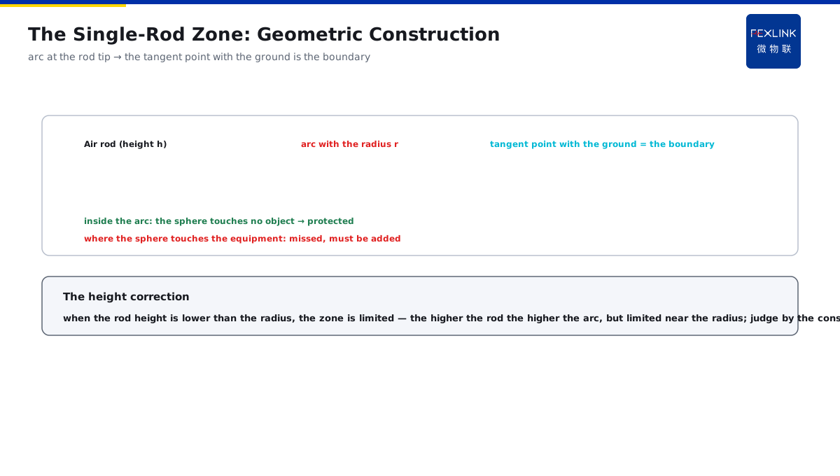
Direct Answer
When designing an air-termination rod, how is "how large a range this rod can protect" determined? The answer: the rolling-sphere method imagines a sphere with a radius equal to the rolling-sphere radius (20/30/45/60 m per the protection class) rolling along the building surface; any point the sphere can touch may be struck, and the air-termination rod/strip must make the sphere touch the air-termination device before touching the protected object; the protection zone is derived by the geometric construction of the rod height and the rolling-sphere radius.
At a factory designed per Class II protection (rolling-sphere radius 45 m), the designer first constructed with the rolling-sphere method: the sphere rolled from the rod tip along the factory roof, the area the sphere surface touched was the "possible-strike area", and with the rod matching the roof, all the protected equipment fell inside the protection arc; after construction, the acceptance by the drawing had no dispute on the air-termination coverage. The key distinction: the rolling-sphere method uses "the sphere rolling along the surface" to judge the possible-strike points — any point the sphere can touch may be struck, and the air-termination device must make the sphere touch itself first; the protection zone is derived by the geometric construction of the rod height and the rolling-sphere radius.
Why:
- The rolling-sphere radius: 20/30/45/60 m per the protection class;
- The judgment logic: any point the sphere can touch may be struck;
- The protection principle: the sphere touches the air-termination device first, not the protected object;
- The zone algorithm: the geometric construction of the rod height + the rolling-sphere radius.
Key insight: "The rolling-sphere method uses 'the sphere rolling along the surface' to judge the possible-strike points — any point the sphere can touch may be struck, and the air-termination device makes the sphere touch itself first; the protection zone is constructed by the rod height and the rolling-sphere radius, with the higher the class the smaller the sphere and the stricter the protection."
At a project three air-termination rods were placed by the atlas without a rolling-sphere check; at the acceptance, the factory corner was found beyond the protection arc, and the sphere directly touched the equipment. After the air-termination strip was added and the construction redone, the corner was covered. Lesson: the protection zone is calculated by the geometric construction, not by placing the rods by the atlas — the rolling-sphere method checks every corner, and the sphere touching the equipment is the missed protection.
Overview: run "how the rolling-sphere radius is taken → how the single-rod zone is constructed → how the multi-rod and strip/mesh combine → how the corners and eaves are handled" as one algorithm cognition. "How large a range the air-termination rod can protect" is not experience but a geometric problem. The rolling-sphere method imagines a sphere with the radius equal to the rolling-sphere radius rolling along the building surface: any point the sphere can touch may be struck, and the air-termination rod/strip must make the sphere touch the air-termination device before touching the protected object; the protection zone is derived by the construction of the rod height and the rolling-sphere radius. The four layers are unfolded below.
An "umbrella" analogy: think of the rolling-sphere method as the canopy of an umbrella. The canopy radius is fixed by the protection class (20 m Class I, 30 m Class II, 45 m Class III), and the ribs are the air-termination rods/strips; the sphere rolling along the building surface is like the canopy moving against the building — the places the canopy (the sphere surface) cannot touch are where it may "leak" (be struck). To keep the whole building leak-free, the canopy must always move above the building and the sphere must touch the air-termination device first; if the rods are too short or too sparsely arranged, the canopy will "stick" to the building, and that place is the missed protection. The umbrella analogy: the rolling-sphere radius = the canopy radius (fixed by the class), the air-termination device = the ribs — the sphere surface not touching the building means no leak, and the place where the sphere touches the building is the missed protection.
1. The Rolling-Sphere Radius: How to Take It
Step one: first look at the relation between the rolling-sphere radius and the protection class.
The rolling-sphere radius:
- Class I protection: 20 m;
- Class II protection: 30 m;
- Class III protection: 45 m (60 m in some standards);
- The higher the class, the smaller the sphere.
Why the higher the class, the smaller the sphere:
- The smaller the sphere, the closer the rolling path to the surface;
- More points can be touched;
- Stricter protection requirements;
- Denser coverage.
How to use it:
- Decide the protection class first;
- Look up the corresponding rolling-sphere radius;
- Use that radius in the construction;
- The radius decides the strictness.
Key insight: "The rolling-sphere radius is taken per the protection class — 20 m Class I, 30 m Class II, 45 m Class III (60 m in some); the higher the class, the smaller the sphere, the closer the rolling to the surface and the stricter the protection — the radius is fixed first, and the construction is accurate."
2. The Single-Rod Protection Zone: How to Construct
Step two: the protection zone of a single air-termination rod is derived by the geometric construction.
The construction logic:
- Draw an arc with the rod tip as the center and the rolling-sphere radius;
- The tangent point of the arc and the ground is the protection boundary;
- The higher the rod, the higher the arc;
- The protection radius varies with the height.
The height correction:
- The rod height lower than the rolling-sphere radius;
- The protection radius per the formula/graphical method;
- The rod height close to the rolling-sphere radius;
- The protection zone limited.
The practical application:
- A single rod protects a point/a small area;
- Large areas need the multi-rod cooperation;
- The construction checks every protected object;
- The sphere touching the equipment is the missed protection.
Key insight: "The single-rod construction — draw an arc with the rod tip as the center and the rolling-sphere radius, and the tangent point of the arc and the ground is the protection boundary; when the rod height is lower than the rolling-sphere radius, the protection zone is limited, and the construction checks every protected object — the sphere touching the equipment is the missed protection."
3. The Multi-Rod and the Strip/Mesh: How to Combine
Step three: large areas use the multi-rod/air-termination strip/mesh combined, and the rolling-sphere method also applies.
The multi-rod combination:
- The arcs of two adjacent rods intersect;
- A protection space is formed between the two rods;
- The spacing checked by the arcs;
- Covering a larger area.
The strip and the mesh:
- The strip laid along the roof edge;
- The mesh covering the roof grid;
- The sphere rolling along the strip/mesh;
- The protection evenly covered.
The combination principle:
- The sphere cannot touch the protected object;
- The strip/mesh/rod complement;
- The corners checked with priority;
- Large areas constructed block by block.
Key insight: "The multi-rod and the strip/mesh combine — the arcs of the adjacent rods intersect to form the protection space with the spacing checked by the arcs; the strip along the edge and the mesh over the roof make the sphere roll along them with even protection; the combination principle is that the sphere does not touch the protected object, with the corners checked with priority."
4. The Corners and the Eaves: The Special Handling
Step four: at the building corners and the eaves, the sphere most easily "touches" the building and must be specially handled.
Why the corners are dangerous:
- The sphere rolls along the surface;
- At the corners, the sphere surface easily touches the building;
- The strike probability concentrates at the corner points;
- Must be protected with priority.
The eave handling:
- The protruding eaves easily touched by the sphere;
- The air-termination strip laid along the eaves;
- The rods set with priority at the eave corners;
- The construction checked point by point.
The practice summary:
- The air termination set with priority at the corners/eave corners;
- The strip/rod cooperation covering;
- Every place checked by the construction;
- The acceptance checked by the drawing.
Key insight: "The corners and the eaves are the high-frequency missed-protection places — when the sphere rolls along the surface, the corners/eave corners are most easily touched; lay the strip along the eaves, set the rods at the eave corners, check point by point by the construction, and confirm the coverage by the drawing at the acceptance."
A four-step on-site way to "check the protection zone": for an air-termination layout, check it in four steps. Step one, fix the radius — look up the rolling-sphere radius per the protection class; step two, construct the single rod — draw the arc with the rod tip and fix the single-rod protection boundary; step three, check the combination — whether the adjacent-rod arcs intersect and the strip/mesh along the roof are continuous; step four, check the corners — the eaves, the eave corners and the protruding equipment checked point by point, the sphere touching being the missed protection. After the four steps, whether the coverage is qualified is clear at a glance. The four-step check: fix the radius (per the class) → construct the single rod (draw the arc at the tip) → check the combination (the arcs intersect, the strip/mesh continuous) → check the corners (the sphere touching point by point is the missed protection) — after the four steps, the coverage qualification is clear at a glance.
5. Product Implementation: The Protection Zone Made Verifiable
WeiWuLian products bring the air-termination protection from the design to verifiable operation:
- The lightning-current monitoring: air-termination operation records;
- The strike location: the actual strike points compared with the protection zone;
- The data review: the missed-protection areas exposed after the fact;
- The loop improvement: the protection-zone design continuously optimized.
The design principle in one sentence: "The construction fixes the zone and the monitoring verifies the coverage — the rolling-sphere construction fixes the protection zone, and the lightning-current monitoring records the actual strikes and the strike points, closing the design-operation loop with the missed protection nowhere to hide."
The three acceptance checkpoints of the rolling-sphere method: after the drawing scheme comes out, the acceptance checks three points. One, the radius correct — look up the rolling-sphere radius per the protection class, consistent with the drawing annotation; two, the coverage complete — every protected object (the equipment, the roof, the eave corners) constructed and confirmed that the sphere does not touch; three, the boundary reserved — the protection-arc boundary keeps a margin from the protected object, and the edge places are often the high-frequency missed-protection areas. With the three points checked, the air-termination layout is qualified. The three acceptance checks: the radius consistent with the class, the coverage checked place by place with the sphere not touching, and the boundary with a margin — the edge places are the high-frequency missed-protection areas, and the layout is qualified only after the checks.
6. Common Understanding Misjudgments
- "The higher the rod, the larger the protection zone": incomplete. When the rod height is close to the rolling-sphere radius, the protection is limited; judge by the construction.
- "Placing the rods by the atlas is enough": wrong. Every protected object must be checked by the rolling-sphere method; the sphere touching the equipment is the missed protection.
- "The rolling-sphere radius is the same": wrong. 20/30/45/60 m per the protection class; the higher the class, the smaller the sphere.
- "The corners need no special handling": wrong. The corners/eave corners are most easily touched by the sphere and must be protected with priority.
- "With the air-termination rod, everything is fine": wrong. The coverage must be verified by the construction, and the lightning-current monitoring rechecks during the operation.
Scope and Limitations
This article explains the rolling-sphere method for the air-termination protection zone (the rolling-sphere radius, the single-rod construction, the multi-rod/strip/mesh combination, the corner/eave handling), applicable to air-termination design checks and acceptance judgments. The specific construction formulas and the graphical-method details follow GB 50057-2010; this article explains only the geometric logic. All cases are anonymized (a factory/a project) and do not refer to any specific customer.