 微物联研究院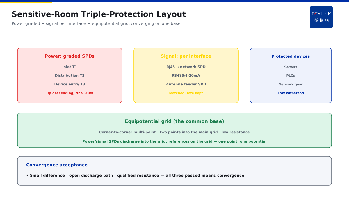
Direct Answer
PLCs, servers and network devices have SPDs only on the power side — why are they still destroyed by surges? The answer: sensitive low-voltage equipment needs three paths protected at once — power inlet SPDs on the power path, matching signal SPDs on the network/control/antenna-feeder paths, and an equipotential bonding grid for the machine room to unify the reference potentials of all paths. Adding only the power path leaves the surge entering through an unguarded signal path or a potential-difference channel — this is the typical blind spot behind "the power SPD is installed but the equipment still fails".
At a machine room, SPDs were installed for the server power, but the server network ports were still destroyed in the storm season. The cause: the network signal path was unguarded — the surge entered through the network cable and hit the motherboard via the signal port. After adding network signal SPDs and an equipotential grid for the room, no further damage occurred. The key distinction: the surge picks the path with no protection — protect the power, signal and grounding paths together; the equipotential grid unifies the reference potentials; protecting only the power path is the typical blind spot.
Why:
- The power path: stage-graded power SPDs on the power inlet;
- The signal path: signal SPDs on the network/control/antenna-feeder lines;
- The grounding path: an equipotential grid for the machine room;
- The coordination core: all three paths converge on the same equipotential.
Key insight: "The surge picks the path with no protection — protect the power, signal and grounding paths together; the equipotential unifies the reference potentials; protecting only the power path is the typical blind spot."
At a factory, a PLC cabinet had power SPDs, but the module communication ports were destroyed after a storm. After adding control-line signal SPDs and the cabinet bonding, it recovered. Lesson: the signal path is the blind spot — only all three paths together hold; patching one path means not protecting all.
Overview: treat "power—signal—grounding" as one whole. The surge enters the sensitive equipment through three routes: the power line (the most direct), the signal lines (network/control/antenna feeder), and the grounding potential difference (entering from the reference ground when the bonding is not done). If any route is unguarded, the surge enters through it. The lightning-protection design of a sensitive room is to close all three routes and make them converge on the same equipotential — the equipotential is the common base of the three routes. The five steps below expand: stage-graded power SPDs, signal SPDs per interface type, the equipotential grid, how the three converge on the same equipotential, and the unified monitoring of the three SPD classes.
Where the surge blind spots of sensitive equipment are: sensitive devices have a low withstand and many interfaces, so the surge has the most channels. There are three typical blind spots. One is the signal interface — network/control/antenna-feeder lines induce surges during a storm, hitting the motherboard/communication chips directly; the chips withstand only tens of volts, and a little energy destroys them. Two is the signal reference ground — if the device reference ground is mixed with the lightning-protection ground (relating to KD-0193), the lightning current enters from the reference ground, showing as "intermittent faults even without a strike". Three is the bonding gap — if one of the cabinets, shields or cable armor is not connected into the equipotential grid, the surge forms a potential difference at that gap and counter-attacks into the device. When judging "the power SPD is installed but it still fails", first ask: was the damaged port the power port or the signal port? If the signal port failed, the signal path is unguarded or there is a bonding gap. The blind spots are not on the power side but on the signal and grounding — first see which port failed, and you know which route is missing.
1. The Power Path: Stage-Graded Power SPDs
Step one: close the most direct power route first.
Why the power is protected first:
- The power line is the most direct surge channel;
- The inlet surge enters the device power directly;
- The power SPD bleeds most of the energy;
- The first-priority path.
The stage configuration:
- The room main inlet graded T1/T2 (relating to KD-0194);
- Distribution/rack cabinets get T2/T3;
- Important equipment power entries get fine protection;
- Stage distance and capacity coordinated.
The power SPD points:
- Uc per the system voltage;
- In/Imax per the boundary capacity;
- Up below the equipment Uw;
- The power path fully covered.
The landing points of the grading: the power SPDs of a sensitive room need at least three stages. The first at the room main distribution inlet (T1, discharging direct/induced energy); the second at the distribution/rack cabinet (T2, clamping the main residual); the third at the important equipment power entries (T3, fine protection, e.g. server dual power, PLC power modules). Between the stages keep the lead distance and descending capacity (relating to the coordination logic of KD-0194). Three checks on site: the first-stage Uc above the highest sustained system voltage; the Up of the second/third stages descending and the final Up strictly below the equipment Uw; the leads of each SPD as short as possible (overlong leads raise the residual, relating to KD-0172). The power path closes the "most direct route" — three stages plus short leads, the energy bled stage by stage.
Key insight: "The power line is the most direct channel — graded at the main inlet, fine at the rack entry; Uc/In/Up per the boundary; the power path closed first."
2. The Signal Path: Signal SPDs per Interface Type
Step two: close the easily-ignored signal route.
Why the signal is protected:
- Network/control/antenna-feeder lines are the dark surge channels;
- The lightning current induces surges in the adjacent cables;
- The signal ports withstand little and are easily destroyed;
- The typical blind spot of power-only protection.
Per interface type:
- Network ports (RJ45) → network signal SPDs;
- Control lines (RS485/4-20mA) → matching signal SPDs;
- Antenna feeder/coaxial → antenna-feeder SPDs;
- Matched per the interface level/rate.
The signal SPD points:
- Interface type matched;
- Transmission rate not reduced;
- Small insertion loss;
- The signal ports protected.
Selection and installation points: a signal SPD cannot be chosen casually — a wrong choice is worse than none (attenuating the signal or mismatching the impedance). Look at four parameters in selection: one, the interface type (RJ45/RJ11/RS485/4-20mA/antenna coaxial — must match); two, the working level and voltage (the working voltage must match the signal level, not filter out the data); three, the transmission rate (network SPDs must support the actual device rate; high-speed links need high-speed SPDs); four, the insertion loss (as small as possible, not affecting the signal quality). Install at the entry before the signal enters the device, as close to the interface as possible, with the wiring as short as possible. The core of signal-SPD selection is "interface matched, rate not reduced, loss minimized" — choose per the interface type and working level, never the wrong type.
Key insight: "The signal is the dark surge channel — network/control/antenna-feeder lines get signal SPDs per the interface; interface matched, rate not reduced; the signal route closed."
3. The Grounding Path: The Machine-Room Equipotential Grid
Step three: build the common base well.
Why the equipotential is the base:
- All three routes finally discharge through the grounding;
- The equipotential unifies the reference potentials of all paths;
- Removing the potential difference between devices (relating to KD-0190/0193);
- The potential difference itself destroys the devices.
The grid practice:
- An equipotential grid in the room (grid/ring);
- Cabinets/devices/cable armor connected into the grid;
- All paths converge on the grid;
- The earth resistance meets the requirement.
Common problems:
- The grid missing/broken;
- Cabinets floating, ungrounded;
- The signal ground mixed (relating to KD-0193);
- The difference destroys the devices.
Construction details of the grid: the grid is not one line but "gridded" grounding. Practice: copper busbars/flat steel laid under the floor, crossing to form a grid (typically 2-3 m mesh); the four corners of the cabinets connected to the grid at multiple points; device enclosures, shields, cable armor and anti-static floor supports all connected into the grid; the grid connected to the main grounding grid at least at two points. On-site checks: the connection resistance between the grid and the cabinets must be low (looseness/oxidation makes that point fail); the grid and the lightning-protection ground handled per the specification (avoid a loop with the signal reference ground, relating to KD-0193); the earth resistance re-checked around the storm season (the FR monitor online, relating to KD-0190). The meaning of gridding is "the potential is the same everywhere" — corner-to-corner multi-point connections, two points into the main grid, effective only with low connection resistance.
Key insight: "The equipotential is the common base of the three routes — a grid in the room, cabinets/armor all connected; all paths converge on the grid; the difference cleared."
4. How the Three Converge on the Same Equipotential
Step four: how the three twist into one.
The convergence logic:
- The power SPD discharges into the equipotential grid;
- The signal SPD discharges into the equipotential grid;
- The device reference ground connected to the grid;
- All three converge at the same point, one potential.
The convergence practice:
- The grid is the common convergence point;
- All discharge paths connected to the grid;
- Avoid each path grounded in isolation;
- Low resistance at the convergence point.
The convergence value:
- One unified discharge path for the surge energy;
- No potential difference between devices;
- The three routes coordinate without fighting;
- The overall protection improved.
The acceptance criteria of convergence: whether the three routes truly converge is accepted with three measurements. One, the potential difference: before commissioning or around the storm season, measure the potential difference between the cabinet enclosures and the device reference grounds — with good bonding, the difference is small both in normal and transient states. Two, the discharge path: after a strike event, see which route's SPD has the most operation records — more operations mean the energy bled through that route, and the path is open. Three, the earth resistance: the resistance from the grid to the main grid meets the requirement (the FR online). Convergence is not "theoretically connected together" but "measured one potential, open discharge path, qualified earth resistance" — all three passed means convergence.
Key insight: "All three converge on the same equipotential — the power/signal SPDs discharge into the grid, the device reference ground on the grid; one point, one potential, no fighting."
5. The Unified Monitoring of the Three SPD Classes
Step five: all three installed — how to manage them.
What to monitor:
- The power SPD state (leakage/temperature/telemetry);
- The signal SPD state;
- The grounding state;
- All three classes seen together.
What to use:
- The FSS intelligent surge protective device with built-in monitoring;
- The FS SPD monitor for unified access;
- Power/signal/grounding data;
- One platform.
The monitoring value:
- Degradation found early on any route (relating to KD-0161);
- Replacement with data (relating to KD-0192);
- Strike events reviewable;
- The triple protection always online.
Placement and duty logic: the monitoring placement follows the paths: power SPDs at each distribution stage, signal SPDs at the device signal entries, grounding at the key grid points. The duty logic in three sentences: normally all three classes stay within their baselines (relating to KD-0162); after a storm, first look at the event records to judge which route carried the energy and which stage did the main discharge; if a route's leakage/temperature keeps rising, that route is degrading (relating to KD-0161) — prompt the replacement early, do not wait until it fails (relating to KD-0192). The value of unified monitoring is turning "all three protected" into "all three watched" — degradation known early, strikes reviewable, the triple protection always online.
Key insight: "Unified monitoring of the three classes — FSS built-in + FS access; power/signal/grounding on one platform; degradation known early, replacement with data."
6. Product Implementation: Triple Protection and Monitoring as One
WeiWuLian products manage the sensitive-room triple protection:
- FSS Intelligent Surge Protective Device: power/signal stage products with built-in monitoring;
- FS SPD Monitor: the three SPD classes connected uniformly;
- Equipotential design: grid + convergence point unified;
- Closed-loop monitoring: degradation warning + event review.
The design principle in one sentence: "Power graded + signal per interface + grounding equipotential, all three protected; FSS/FS monitored uniformly — the surge picks the unguarded path; all three closed means it holds."
7. Common Protection Misjudgments
- "Only the power": ignoring the signal and grounding. Result: signal ports/potential differences destroy the devices. Correct: protect all three.
- "The signal ports need no protection": ignoring the dark channel. Result: network/communication ports destroyed. Correct: signal SPDs per the interface.
- "The equipotential is optional": ignoring the base. Result: the difference destroys the devices. Correct: the equipotential grid.
- "Each route grounded in isolation": ignoring the convergence. Result: inconsistent reference potentials. Correct: converge on the same equipotential.
- "Installed and forgotten": ignoring the monitoring. Result: degradation unknown. Correct: unified monitoring of all three.
Scope and Limitations
This article gives the triple-protection coordination design for sensitive-room equipment (stage-graded power SPDs, signal SPDs per interface, the equipotential grid, three-route convergence, unified monitoring), applicable to the lightning-protection design and optimization of PLC/server/network equipment. The exact parameters and requirements follow GB 50343-2012 and the manufacturers' data; this article explains only the coordination design logic and points. All cases are anonymized (a machine room, a factory) and do not refer to any specific customer.