 微物联研究院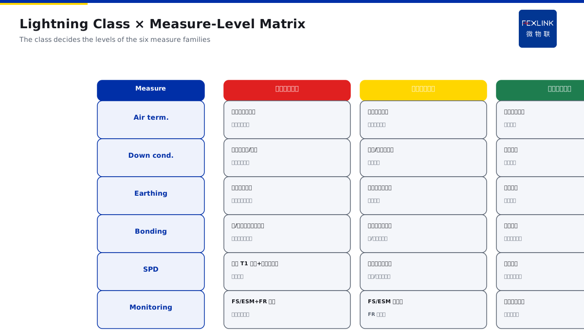
Direct Answer
For a new build in a high-storm region, how do you go from lightning risk all the way to an executable measures checklist? The answer: a new build should first set the lightning-protection class from the annual expected strike count N and the building importance, then set the configuration levels of air termination, down conductors, earthing, equipotential bonding and the SPD stages per class, and finally land on a measures checklist — starting from the class rather than from a product list, so it is neither overdone nor gapped.
At a new park in a high-storm region, the design piled up SPDs directly "the more the better", ending over budget while some points still lacked protection. Restarting the flow: set the class from N and the building importance → set the air-termination/down-conductor/earthing/bonding/SPD levels per class → output a class-matched measures checklist. The key distinction: lightning design derives measures from the class, not stacks configurations from products — N sets the class, the class sets the level, the level sets the checklist; neither overdone nor gapped.
Why:
- Step one: set N and the lightning class from the building importance;
- Step two: set the air termination and down conductors per class;
- Step three: set the earthing and equipotential bonding per class;
- Step four: set the SPD stages and monitoring per class, then output the checklist.
Key insight: "Start from the class, not from the products — N sets the class, the class sets the level, the level sets the checklist; neither overdone nor gapped."
At a park, SPDs were piled from a product list, but equipment still failed in the storm season; after deriving by class, the down-conductor and bonding gaps were filled, and the budget became more reasonable. Lesson: class first, measures second — the measures follow the class, and only a right direction leaves no gap.
Overview: run "risk→class→measures→checklist" as a reproducible flow. The right order of lightning design for a new build is not choosing products first, but answering three questions first: how high is the strike risk of this project (what is N), how important is this project (which building class), and to what level must it be configured. With the three answers, the measures checklist derives itself — each building class corresponds to a clear set of requirements for air termination, down conductors, earthing, bonding and SPDs. The five steps below expand: setting N and the class, setting air termination and down conductors, setting earthing and bonding, setting the SPD stages and monitoring, and outputting a class-matched measures checklist.
The meaning of N and of a high-storm region: N (the annual expected strike count) consists of three parts: the local storm days (naturally high in high-storm regions), the equivalent area of the building (larger with height and footprint), and correction factors (terrain and surroundings). N is not "it feels stormy" but a computable engineering quantity. The two meanings of a high-storm region: one, the same building has a higher N and may go up a class; two, the measure levels are configured higher per class — the high region is not "more products" but "every measure done to a higher level". The right design action is computing N by the specification first, then setting the class against the class table, keeping the calculation notes for review. N is computable and the class is checkable — calculate first, then set the class; the "high" of the high region lies in the level, not the quantity.
The decision meaning of a high-storm region: a high-storm region is not solved by "a few more air rods and a few more SPDs" — a higher N may raise the class by one level, and a raised class upgrades the level of every measure together: stricter air-termination coverage, denser down conductors, stricter earth resistance, a larger bonding range, fuller SPD stages, more monitoring points. To judge whether the design is "configured in place", see whether the checklist strictly matches the class: with the class set, every checklist item can state its basis; every item can trace back to the class. The "high" of the high region lies in the level of every measure, not the product count — the level follows the class, and the checklist is then in place.
1. Step One: Set N and the Lightning Class
Step one: calculate the risk and set the class first.
How N is computed:
- The annual expected strike count N per the specification formula;
- Related to the local storm days and the equivalent building area;
- N reflects how many strikes this project expects per year;
- Naturally high in high-storm regions.
How the class is set:
- Against the specification with N and the building importance;
- Classes one/two/three correspond to different levels;
- Dense-population/important buildings take the higher;
- The class decides all later measure levels.
Common errors:
- Skipping the calculation and piling products;
- A low class leaving gaps;
- A high class overdoing;
- Class first, measures second, no error.
The constitution of N: N consists of three parts: the local storm days (naturally high in high-storm regions), the equivalent building area (larger with height and footprint), and the correction factors (terrain and surroundings). N is not "it feels stormy" but a computable engineering quantity. The right design action is computing N by the specification first, then setting the class against the class table, keeping the calculation notes for review. Calculate N first, then set the class — N reflects the expected strikes per year, the class decides all measure levels; skipping the calculation and piling products is the root error.
2. Step Two: Set the Air Termination and Down Conductors
Step two: set the air termination per class.
The air-termination configuration:
- The air-termination mode per class (rod/strip/mesh);
- The protected zone covering the objects;
- High-storm regions/class one stricter;
- The air termination is the first line.
The down-conductor configuration:
- The spacing/count per class;
- The down-conductor paths continuous, sections sufficient;
- Avoid overlong leads raising the voltage drop;
- Clear discharge paths.
Relating to the later text:
- The air termination decides where the current goes;
- The down conductors lead the current to the earthing grid;
- Sections/continuity are the check focus;
- Air termination + down conductors form the discharge channel.
The engineering points of the air termination and down conductors: the air-termination device (rod/strip/mesh) "catches the strike and lets the current follow a planned path", with the configuration upgraded per class: class one stricter (the protected zone covering all objects, denser meshes), class three looser. The down conductors are the "discharge channel" between the air termination and the earthing, with three points: one, the spacing and count per class (higher class, denser and shorter); two, the path continuous (air termination → down conductor → grid without a break — a break re-routes the current); three, the section sufficient (the channel cannot be a thin wire, relating to KD-0195's on-site checks). High-storm projects often save material on the down conductors — saving them means the current cannot discharge even if caught, as if not caught. Air termination + down conductors form the discharge channel — coverage, continuity and section, all three required.
Key insight: "Set the air termination and down conductors per class — the mode and spacing upgrade with the class; the path continuous, the section sufficient; a complete discharge channel."
3. Step Three: Set the Earthing and Equipotential Bonding
Step three: set the earthing base per class.
The earthing configuration:
- The earth-resistance requirement per class;
- The earthing-grid/electrode arrangement;
- High-storm regions stricter, connections reliable;
- The earthing is the discharge end.
The bonding configuration:
- The bonding range per class;
- The total/local equipotential bonding;
- Metal pipes/structures connected;
- The potential difference removed (relating to KD-0190/0193).
Common gaps:
- The earth resistance not meeting;
- The bonding range not enough;
- Connection points loose/corroded;
- An unstable base destabilizes everything.
The class differences of earthing and bonding: the configuration upgrades with the class mainly in three places. One, the earth-resistance requirement — higher class, stricter; high-storm projects must meet the class (the FR monitor online, relating to KD-0190). Two, the electrode arrangement — higher class, denser grids/electrodes, fuller discharge paths. Three, the bonding range — higher class, larger coverage of the total/local bonding, with metal pipes, structures and cabinets connected more fully. Write these three into the checklist per class and check them item by item during construction. The common gap is "resistance meets but the range does not" — the earthing is done, yet the difference enters the equipment from an unconnected metal structure (relating to KD-0193). The earthing is the discharge end and the bonding removes the difference — the resistance meets per class, the range covers per class, both written into the checklist.
Key insight: "Set the earthing and bonding per class — the resistance meets, the range covers per class; all metal structures connected; a stable base makes the measures stand."
4. Step Four: Set the SPD Stages and Monitoring
Step four: set the SPDs and monitoring per class.
The SPD configuration:
- The power-SPD stages per class (relating to KD-0194);
- Signal paths per interface (relating to KD-0196);
- Capacity/residual per boundary;
- Higher class, fuller configuration.
The monitoring configuration:
- The FS/ESM SPD monitor for the states;
- The FR monitor for the earthing;
- High-storm/important points monitored online;
- Degradation known early (relating to KD-0161).
The configuration logic:
- The class decides the SPD count and level;
- The monitoring follows the risk;
- Power/signal/grounding all three;
- No route left out.
The class configuration table of SPDs and monitoring: the power SPDs set the stages per class (class-one main inlets T1 stricter, class three simpler, relating to the coordination logic of KD-0194); the signal paths get SPDs per interface (network/control/antenna feeder, relating to the three routes of KD-0196). The monitoring follows the risk: high-storm/important points get the FS/ESM SPD monitor for the states (leakage/temperature/telemetry, degradation early, relating to KD-0161) and the FR monitor for the earthing (re-checked around the storm season, relating to KD-0190). The higher the class, the fuller the SPD stages and the denser the monitoring points. Write "which stage gets what capacity, which points get monitoring" into the checklist — with it in the checklist, construction misses nothing. The SPD stages upgrade with the class and the monitoring follows the risk — FS/ESM for the SPD states, FR for the earthing; written into the checklist, construction misses nothing.
Key insight: "Set the SPDs and monitoring per class — power graded, signal per interface, monitoring with the risk; FS/ESM for the states, FR for the earthing; higher class, fuller configuration."
5. Output a Class-Matched Measures Checklist
Step five: land the derived results as a checklist.
The checklist structure:
- One row per building class;
- Each row: air termination/down conductors/earthing/bonding/SPD/monitoring;
- Each column: the requirement and quantity;
- One checklist to the end.
The checklist use:
- Design and construction have a basis;
- Acceptance has reference items;
- The budget is estimable;
- No gap, no excess, no waste.
The landing points:
- The checklist strictly matching the class;
- Each item with parameters/quantities;
- High-storm regions from the higher, not the lower;
- The checklist updated with the project.
The checking and updating of the checklist: the measures checklist is not written once and done; it passes three checks. One, the class-match check — every measure can trace back to the class (if the reason for an item cannot be stated, it is product piling). Two, the coverage check — the six categories of air termination/down conductors/earthing/bonding/SPD/monitoring all present (one missing is a gap). Three, the parameter check — each item with capacity, residual, spacing and quantity (a checklist without parameters cannot be referenced at acceptance). When the project changes (building height, function), update N and the class, and the checklist follows. The checklist is "traceable, full-coverage, with parameters" — every item back to the class, all six present, parameters acceptable; updated as the project changes.
Key insight: "Output the class-matched checklist — one row per class, every column configured; design/acceptance/budget all have a basis; no gap, no excess, no waste."
6. Product Implementation: From the Checklist to Online Monitoring
WeiWuLian products configure new-build lightning protection in place:
- FS/ESM SPD Monitor: the SPD states of every stage online;
- FR Earth-Resistance Monitor: the earthing state/resistance online;
- Class-matched checklist: measures strictly matched to the class;
- Closed-loop monitoring: degradation early + event review.
The design principle in one sentence: "N sets the class, the class sets the level, the level sets the checklist — air termination/down conductors/earthing/bonding/SPD configured per class, FS/ESM + FR monitoring as the backstop."
7. Common Design Misjudgments
- "Piling products directly": skipping the class. Result: overdone or gapped. Correct: class first, measures second.
- "The class set casually": ignoring N. Result: level mismatch. Correct: compute N, set the class.
- "Air termination only": ignoring earthing/bonding. Result: no discharge place. Correct: configure the whole chain.
- "Power SPDs only": ignoring signal/earthing (relating to KD-0196). Result: blind-spot damage. Correct: all three routes.
- "The checklist detached from the class": ignoring the match. Result: acceptance without a basis. Correct: output the checklist per class.
Scope and Limitations
This article gives the flow from lightning class to a measures checklist for new builds in high-storm regions (N and the class, air termination and down conductors, earthing and bonding, SPDs and monitoring, the class-matched checklist), applicable to new-build lightning design. The exact calculation and requirements follow GB 50057-2010, GB 50343-2012 and the manufacturers' data; this article explains only the derivation flow and the checklist logic. All cases are anonymized (a park in a high-storm region) and do not refer to any specific customer.