 微物联研究院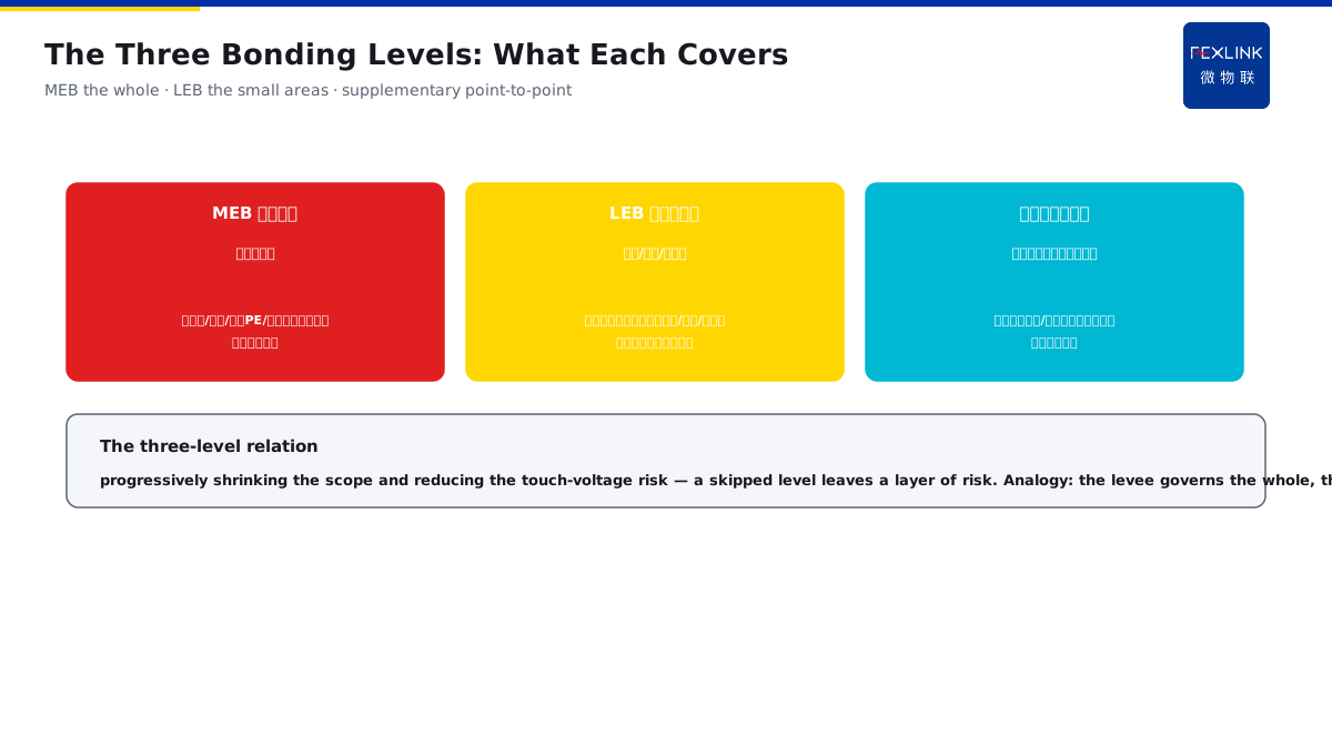
Direct Answer
There are a lot of terminal boards like MEB and LEB on the drawing — how do you distinguish their roles and locations? The answer: the main equipotential bonding (MEB) connects the metal mains — water supply/drainage, HVAC, the electrical PE and the like — at the building service entrance; the local equipotential bonding (LEB) makes another loop in dangerous or sensitive small areas such as bathrooms, computer rooms and explosion-proof zones; the supplementary bonding directly bridges between simultaneously touchable exposed conductive parts; the three levels progressively shrink the scope and reduce the touch-voltage risk.
At a project the drawing showed the MEB, but the bathroom only had half the local bonding done — the metal parts of the shower area were not connected to the LEB terminal board; at a leakage fault, a touch voltage appeared between the shower head and the floor drain, and the user got an electric shock. After the LEB connections were completed, the touch voltage was limited to the safe range at the next fault. The key distinction: the three levels progressively shrink the scope — the MEB covers the whole building (connecting the metal mains at the service entrance), the LEB covers the dangerous small areas (bathroom/computer room/explosion-proof zone), and the supplementary bonding covers two simultaneously touchable metal parts; the smaller the scope, the more targeted against the touch voltage, and a skipped level leaves a layer of risk.
Why:
- The MEB main bonding: at the building service entrance, connecting the water/HVAC/electrical PE metal mains;
- The LEB local bonding: a loop made again in the dangerous/sensitive small areas such as the bathroom/computer room/explosion-proof zone;
- The supplementary bonding: directly bridging between simultaneously touchable exposed conductive parts;
- The three-level relation: progressively shrinking the scope, reducing the touch-voltage risk.
Key insight: "The three levels progressively shrink the scope — the MEB covers the whole (connecting the metal mains at the service entrance), the LEB covers the dangerous small areas (bathroom/computer room/explosion-proof zone), and the supplementary bonding covers simultaneously touchable metal parts; a skipped level leaves a layer of touch-voltage risk."
At a computer room the MEB was done but the cabinet area had no LEB; at a device leakage the potential difference appeared between adjacent cabinets, and the maintenance worker got shocked when touching; after the cabinet-area LEB was added, the potential difference was limited. Lesson: the MEB cannot govern the small areas — sensitive areas such as computer rooms and bathrooms must have the LEB added, and a large-scope bonding cannot replace the local protection.
Overview: run "which level covers what → why the key areas must have the LEB → the bonding-conductor cross-section → the construction acceptance" as one discrimination. On the bonding drawing the MEB and LEB terminal boards are common, plus the supplementary bonding; the three are often mixed up and the construction often becomes a formality. In fact the three levels have separate roles: the MEB governs the whole building, the LEB governs the dangerous/sensitive small areas, and the supplementary bonding governs two simultaneously touchable metal parts — progressively shrinking the scope and progressively reducing the touch-voltage risk. The four layers are unfolded below.
An "levee-cofferdam-bridge" analogy: think of the three bonding levels as flood control. The MEB is the levee — a whole ring along the building service entrance, blocking the "main flows" of the water supply/drainage, the HVAC and the electrical PE; the LEB is the small cofferdam — a loop made again in the bathroom, the computer room and the explosion-proof zone, separately surrounding the places where water easily spills; the supplementary bonding is the direct bridge — a jump board between two devices that can be touched at the same time, pulling their potentials level. The levee governs the whole, the cofferdam governs the local, and the jump board governs point-to-point — with the three cooperating, the water (the potential difference) does not leak. The levee-cofferdam-bridge analogy: the MEB = the levee governing the whole, the LEB = the cofferdam governing the local, the supplementary bonding = the jump board governing point-to-point — with the three cooperating, the potential difference does not leak.
1. The Three Bonding Levels: Which Level Covers What
Step one: first tell apart the roles of the MEB, the LEB and the supplementary bonding.
The MEB main bonding:
- Location: the building service entrance (near the main distribution);
- Bonding objects: the metal mains — water supply/drainage, HVAC, the electrical PE, the lightning down-conductors;
- Role: unifying the potential reference of the whole building;
- Scope: the whole building.
The LEB local bonding:
- Location: small areas such as the bathroom, the computer room and the explosion-proof zone;
- Bonding objects: the touchable metal parts in the area (the shower head, the cabinet, the pipes);
- Role: eliminating the potential differences in a small scope;
- Scope: the dangerous/sensitive small areas.
The supplementary bonding:
- Location: between two simultaneously touchable exposed conductive parts;
- Bonding objects: two device shells/two metal parts;
- Role: directly bridging to eliminate the touch voltage;
- Scope: point-to-point.
Key insight: "The three roles in one sentence — the MEB governs the whole (connecting the metal mains at the service entrance), the LEB governs the small areas (bathroom/computer room/explosion-proof zone), and the supplementary bonding governs point-to-point (simultaneously touchable metal parts); the scope shrinks progressively and the touch voltage reduces progressively."
2. Why the Key Areas Must Have the LEB
Step two: the MEB covers the whole building — why make the LEB again in the small areas?
The necessity of the LEB:
- The MEB governs the whole reference but not the local details;
- The bathroom is wet and people are barefoot, with a high touch-voltage risk;
- The computer room is densely equipped with many shells and is sensitive to the potential difference;
- A spark in the explosion-proof zone can ignite.
The risks of no LEB:
- The potential difference between the local metal parts and the reference not eliminated;
- The touch voltage may exceed the safe threshold;
- People hurt at a leakage fault;
- The sensitive equipment disturbed by the potential difference.
How to do the LEB:
- All the touchable metal parts in the area bonded;
- Connected to the LEB terminal board nearby;
- The terminal board then connected to the MEB;
- The key areas checked point by point.
Key insight: "The MEB cannot govern the local — the bathroom is wet and barefoot, the computer room is densely equipped, and the explosion-proof zone fears sparks, so the LEB must be made; all the touchable metal parts in the area are bonded to the LEB terminal board, and the board is then connected to the MEB."
3. The Bonding-Conductor Cross-Section: How to Choose
Step three: the cross-section is chosen by "scope + role", not by one unified value.
The cross-section of the MEB:
- Taken per the service-entrance PE cross-section;
- The copper/steel materials per the standard multiples;
- The main bonding conductors are larger;
- Meeting the mechanical strength and the current-carrying capacity.
The cross-section of the LEB:
- Taken per the equipment condition of the area;
- Not less than the standard minimum;
- Covering the local bonding demand;
- Also meeting the mechanical strength.
The cross-section of the supplementary bonding:
- Taken per the current demand of the bonded object;
- Meeting the touch-voltage limit;
- The mechanical strength up to standard;
- The specific values expanded in KD-0226.
Key insight: "The cross-section is chosen by 'scope + role' — the MEB per the service-entrance PE, the LEB per the area equipment, and the supplementary bonding per the object current; the main bonding conductors are larger, and the specific values per the standard and KD-0226."
4. Construction Acceptance: How to Check the Continuity
Step four: the bonding most fears "drawn but not connected, connected but not continuous" — the acceptance must verify the real connection.
What to check:
- The terminal-board locations consistent with the drawing;
- The bonding objects checked point by point;
- The conductor specification and cross-section;
- The connection points firm and reliable.
How to check the continuity:
- Measure the bonding resistance with an instrument;
- Actually measured with a multimeter/micro-ohmmeter;
- Check the crimping/welding of the connection points;
- Sample the key areas.
The relation to the monitoring:
- The ESP watches the N-PE potential difference continuously;
- The bonding degradation can be found by the trend;
- Rechecked after a thunderstorm/fault;
- The data speaks, not the visual.
Key insight: "The acceptance verifies the real connection — the terminal-board locations, the bonding objects, the wire specification and the connection-point firmness are checked item by item; the bonding resistance is measured with an instrument, the ESP continuously watches the N-PE difference, the degradation has a trend and the acceptance has data."
The high-frequency "skipped/mistaken" points of the three levels: three common problems in the construction. One, drawn but not connected — the drawing has the MEB/LEB but the on-site terminal-board locations do not match; two, connected but not wired — the terminal board is installed but the shower head, the cabinet and other bonding objects are not wired; three, wired but not measured — the wire is connected but no continuity test is done, and the loose/crimp problems cannot be seen. The common root of the three problems: treating the bonding as "a matter on the drawing" instead of "a matter connected on site and measured at the terminals". The acceptance closes the loop in "drawing → site → instrument": first match the drawing, then verify the on-site bonding objects, and finally measure the bonding resistance with an instrument. The high-frequency problems: drawn but not connected (the terminal board does not match), connected but not wired (the bonding objects not wired), wired but not measured (the loose cannot be seen) — the acceptance closes the loop in drawing → site → instrument, treating the bonding as "a matter connected on site".
5. Product Implementation: The Three Levels Made Visible
WeiWuLian products bring the bonding system into verifiable monitoring:
- The ESP Zero-Voltage Monitor: the N-PE potential difference continuously monitored;
- The bonding state: the bonding effect of the key areas quantified;
- The system view: the MEB/LEB area states on one screen;
- The data loop: the potential difference verified after a leakage/strike.
The design principle in one sentence: "The three levels progressively shrink the scope — the MEB governs the whole, the LEB governs the small areas, and the supplementary bonding governs point-to-point; the ESP watches the potential difference and the bonding effect is quantified, making the three levels visible."
6. Common Understanding Misjudgments
- "With the MEB, no LEB is needed": wrong. The MEB governs the whole reference and cannot govern the local details of the bathroom/computer room.
- "The LEB only in the bathroom": wrong. The dangerous/sensitive areas such as the computer room, the explosion-proof zone and the wet areas all need it.
- "Bonding means just wiring a line": wrong. The objects, cross-section and continuity must all be checked — a wire connected does not mean a circuit.
- "The acceptance by visual is enough": wrong. The bonding resistance must be measured with an instrument; the visual cannot see a loose connection.
- "The wire thickness does not matter": wrong. The cross-section is chosen by scope + role; otherwise the mechanical strength and the current-carrying capacity are insufficient.
Scope and Limitations
This article discriminates the three bonding levels (the MEB/LEB/supplementary bonding) — their roles, locations, cross-section selection and acceptance methods — applicable to bonding design and construction judgments. The specific cross-section values and terminal-board practices follow GB 50057-2010 and GB 51348-2019; this article explains only the level logic. All cases are anonymized (a project/a computer room) and do not refer to any specific customer.