 微物联研究院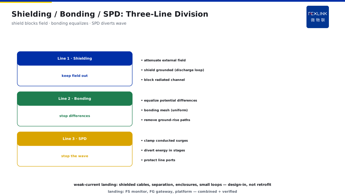
Direct Answer
When doing weak-current system protection, we keep hearing about LEMP — how is it different from the surge that a power-side SPD protects against? The answer: LEMP is the rapidly changing electromagnetic field produced by the huge strike current around it; it both conducts along wires (which an SPD can clamp) and induces interference/damage voltages in closed signal loops as a spatial magnetic field — the latter cannot be blocked by a power SPD and must be attenuated by shielding, equipotential bonding, and lightning-protection zoning.
At one data center, signal lines were frequently disturbed: power-side SPDs were complete and surge records normal, yet communication ports still failed intermittently. Investigation: the room had no shielding (unshielded cables laid parallel over long runs); during strikes the field induced high voltage in signal loops. Rectification: shielded signal cables + shield grounded + shorter parallel runs. Distinction core: LEMP has two channels — SPD can stop the conducted channel, shielding is required for the radiated channel; adding a power SPD alone cannot stop magnetic induction.
Because:
- LEMP is a "field," not a "wave": the strike current creates a rapidly changing electromagnetic field;
- Conducted coupling can be clamped: line-borne surges can be stopped by SPDs;
- Radiated coupling defeats SPDs: field-induced loop voltages need shielding;
- Division of labor: shielding / equipotential bonding / SPD each cover a segment.
Key insight: "SPD for conduction, shielding for radiation" is the division principle of LEMP protection. Fail to separate the channels and protection is half-missing — weak-current damage is usually in the "field," not the "wave."
At one plant, control-room signal ports failed repeatedly; upgrading to more advanced power SPDs did nothing. Rectification: signal SPDs + shielded cables + equipotential bonding solved it. Lesson: protecting LEMP as an ordinary surge misses the radiated channel — shielding + bonding is the key to weak-current protection.
1. The Field Source of LEMP: Radiation and Near-Field Magnetic Field from Strike Current
Step one: where LEMP comes from.
Field-source composition:
- The strike current itself (hundreds of kA);
- The rapidly changing current creates a magnetic field (large di/dt);
- The electric field (influence of high potential in space);
- The radiated field (electromagnetic waves propagating outward).
Near field and far field:
- Near field (equipment near the strike point): magnetic field dominant;
- Far field (far away): electromagnetic-wave radiation;
- Weak-current equipment is usually in the near field;
- The near-field magnetic field is the main threat.
Affected objects:
- Closed loops (larger area → stronger induction);
- Long signal lines (antenna effect);
- Sensitive chips (low damage threshold);
- Cables parallel/adjacent to the lightning-current path.
Key insight: "the di/dt of the strike current creates the magnetic field" is the source of LEMP. Magnetic coupling does not ask "was it struck directly" — it asks about the relationship between the loop and the field.
2. Conducted vs Radiated Coupling: Two Invasion Channels
Step two: how LEMP enters equipment.
Channel 1: conducted coupling:
- Strike current/surge travels along conductors;
- Paths: power lines, signal lines, earthing conductors;
- Feature: a clear path, can be clamped by SPDs;
- Protection: staged power/signal SPDs.
Channel 2: radiated coupling:
- The field induces voltage in closed loops;
- Path: spatial coupling (no physical connection needed);
- Feature: no path, SPDs cannot stop it;
- Protection: shielding + smaller loops + equipotential bonding.
Comparison of the two channels:
- Conducted: visible (surge records/clear damage points);
- Radiated: invisible ("unexplained" damage);
- Conducted: single-point protection (SPD) suffices;
- Radiated: overall design (shielding/wiring) is required.
Key insight: "conducted has a path, radiated has none" determines the different protection methods. Looking only at the conducted channel, radiated damage will never be traced to its cause.
3. Why Power SPDs Are Ineffective Against the Magnetic-Induction Part
Step three: where the SPD boundary lies.
How SPDs work:
- Clamp surges (voltage/current) on conductors;
- Divert surge energy along conductors to earth;
- Protect the protected line port.
Features of magnetic induction:
- The voltage arises "in space" (not along the conductor);
- Induced voltage distributes along the whole loop;
- No fixed entry point (SPD cannot be positioned);
- Damage occurs at any weak point of the loop.
Why it is ineffective:
- SPDs can only handle "on-line" surges;
- Magnetic induction is "in-loop" voltage;
- Induced voltage still exists beyond the SPD clamp point;
- Adding more SPDs does not change field coupling.
Key insight: "SPD governs the line, shielding governs space" is the boundary. Power SPDs are naturally ineffective against the magnetic-induction part — this is not an SPD quality problem; it is a different channel.
4. What Shielding, Equipotential Meshes, and SPDs Each Handle
Step four: how protection is divided.
Shielding handles:
- Attenuating the external magnetic field (shield layers/rooms/cabinets);
- Blocking the radiated-coupling channel;
- Grounding the shield layer (forming a discharge loop);
- Keeping internal loops free from external-field influence.
Equipotential bonding handles:
- Equalizing potential differences between equipment;
- Eliminating ground-rise paths;
- Equipotential meshes (uniform spatial potential);
- Working with shielding and SPDs to form a complete system.
SPDs handle:
- Clamping conducted surges;
- Diverting energy in stages;
- Protecting line ports;
- Coordinating with shielding/bonding.
Division relationship:
- Shielding: keep the "field" out (first line);
- Bonding: keep the "difference" from arising (second line);
- SPD: keep the "wave" from traveling (third line);
- All three together = complete LEMP protection.
Key insight: "shielding blocks the field, bonding equalizes the difference, SPD diverts the wave" — a three-line division. Each covers a segment; none is dispensable — combined protection is the right answer for LEMP.
5. The Position of LEMP Protection in Weak-Current System Design
Step five: how to land it in design.
Design positions:
- Scheme stage: define lightning-protection zones (LPZ);
- Wiring stage: cable shielding, smaller loops;
- Construction stage: equipotential bonding, shield grounding;
- Operation stage: SPD monitoring, protection verification.
Weak-current system points:
- Prefer shielded cables for signal lines;
- Keep cables away from lightning-current paths (spatial separation);
- Shield rooms/cabinets (metal enclosure + grounding);
- Minimize loop area (close laying/twisting).
Verification methods:
- SPD state monitoring (conducted channel);
- Shield-continuity testing (radiated channel);
- Equipotential-resistance testing (system equalization);
- Lightning-event review (protection effectiveness).
Key insight: "LEMP protection must enter the design, not be an afterthought." The shielding/wiring/bonding of weak-current systems is decided at the scheme stage; operation relies on monitoring verification.
6. Product Landing: Intelligent Lightning-Protection On-Line Monitoring
FEXLINK products land LEMP protection:
- FS SPD Monitor: conducted-channel protection state (SPD effectiveness);
- FG Lightning-Protection Intelligent Gateway: aggregation of multi-channel monitoring data + event records;
- Platform: lightning events + SPD state + trend analysis;
- Combined with shielding/bonding design to form complete protection.
Design principle in one sentence: "SPD for conduction, shielding for radiation, bonding for the system." Three channels, three-line protection — LEMP protection is then complete.
7. Common Protection Misconceptions
- Installing only power SPDs: ignoring the radiated channel. Consequence: weak-current equipment still damaged. Correct: shielding + signal SPDs.
- Treating LEMP as an ordinary surge: protecting with a surge plan. Consequence: magnetic induction unprotected. Correct: protect field and wave by channel.
- Shield layers not grounded: shielding rendered useless. Consequence: no shielding effect. Correct: ground shield layers properly.
- Ignoring loop area: long parallel runs. Consequence: large induced voltage. Correct: close laying/twisting.
- No protection verification: installed but not tested. Consequence: weaknesses unknown. Correct: periodic verification of shielding/bonding/SPDs.
Scope and Limitations
This article explains the difference between LEMP (lightning electromagnetic pulse) and ordinary surges, the two coupling channels, and the corresponding protection division, applicable to lightning-protection design for weak-current systems (signal/control/communication). Specific shielding methods, equipotential meshes, and SPD selection must follow on-site LPZ classification and codes (GB 50343, GB 50057, etc.); LEMP protection involves multi-discipline coordination and is recommended to be designed uniformly at the scheme stage. All cases are anonymized (a certain data center/a certain plant) and do not refer to any specific customer.