 微物联研究院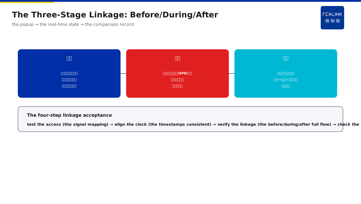
Direct Answer
With an existing lightning-warning platform, how can it be linked with the on-site lightning-protection monitoring so that the state of the area is automatically reviewed when the alarm sounds? The answer: access the third-party graded warning signals through the dry-contact/RS485 of the FG intelligent lightning-protection gateway — the warning grade, as the external event tag, is aligned on the time axis with the on-site FL, FS and FR data; during the thunderstorm, the lightning current, SPD and earthing state of the area are automatically popped up; after the storm, the "warning — strike — device-state" comparison record is automatically generated; the key of the linkage is the unified clock and the event tag.
At an airport, there was already a lightning-warning platform, and when the warning sounded, the operator still had to log into the monitoring system manually to look at the SPD and earthing state one by one, being busy during the thunderstorm. After the graded warning signal was accessed into the FG gateway through the dry contact: the warning automatically tagged the time axis when it arrived; during the storm, the lightning current, the SPD operation and the earthing resistance of the area were automatically popped up; after the storm, the comparison record was automatically generated, and one storm review was completed in ten minutes. The key distinction: the linkage is not "the two systems each sounding their own" — the warning grade, as the external event tag, is aligned with the on-site data on the time axis, the state is automatically popped up during the storm, and the comparison record is automatically generated after the storm; the unified clock and the event tag are the key premise of the linkage.
Why:
- The interface access: the dry contact/RS485 receives the graded signal;
- The time-axis alignment: the warning event aligned with the monitoring data;
- The in-storm linkage: the area state automatically popped up;
- The post-storm review: the comparison record automatically generated.
Key insight: "The linkage relies on the time-axis alignment — the warning grade, as the event tag, is aligned with the FL/FS/FR data, the state is automatically popped up during the storm, and the comparison record is automatically generated after the storm; the unified clock and the event tag are the key premise."
At a chemical park, the warning platform and the monitoring system were independent of each other; during the storm, when the warning sounded, the operator spent half an hour confirming the equipment state by phone, missing the disposal window. After the FG linkage, the warning trigger automatically reviewed the area state, and the disposal was shortened from 30 minutes to 3 minutes. Lesson: the two skins have no linkage value — the warning and the monitoring must be aligned on the time axis and automatically reviewed, and the disposal has speed.
Overview: run "how the warning signal is accessed → how the time axis is aligned → how the before/during/after actions are designed → why the clock and the tag matter" as one warning-linkage cognition. Access the third-party graded warning signals through the dry-contact/RS485 of the FG gateway; the warning grade, as the external event tag, is aligned on the time axis with the on-site FL, FS and FR data; during the thunderstorm, the lightning current, SPD and earthing state of the area are automatically popped up; after the storm, the comparison record is automatically generated. The four layers are unfolded below.
A "sentinel messenger" analogy: think of the warning linkage as the sentry tower passing the order to the lookout. The sentry tower (the warning platform) discovers the enemy (the approaching thunderstorm) and blows the horn (the graded signal), but the horn sound must reach the lookout (the FG gateway) before anyone looks at the field — the horn sound pulls the lookout through the "messenger rope" (the dry contact/RS485), and the lookout immediately "hoists the flag" (the event tag) and reviews the "lookout records" (the FL/FS/FR data) of the area. Without the unified clock, the time when the sentry tower blows the horn and the time when the lookout records cannot match, and the review cannot tell what the field looked like when the horn sounded; without the event tag, the "this enemy" observation cannot be found in the record pile. The linkage is not the two places each busy with their own — but the horn sounds and the observation arrives at once. The sentinel-messenger analogy: the warning = the sentry tower blowing the horn, the FG = the lookout hoisting the flag and reviewing the records; the unified clock = the horn sound and the record time consistent, and the event tag = retrievable in the record pile — the horn sounds and the observation arrives at once.
1. The Signal Access: How to Connect the Dry Contact/RS485
Step one: first look at the interface where the warning signal accesses the FG gateway.
The dry-contact access:
- The contacts of the graded warning signal;
- The passive contacts accessed into the gateway;
- The grade mapped as the event;
- Simple and reliable.
The RS485 access:
- The serial protocol docking;
- The warning-grade data uploaded;
- Carrying the grade and the time information;
- The information more complete.
The access points:
- The signal-grade mapping;
- The wiring standard;
- The test and the joint commissioning;
- Confirming the correct trigger.
Key insight: "Two interfaces access — the dry contact is simple and reliable with the passive contacts (the grade mapped as the event), and the RS485 is complete with the serial data (carrying the grade and the time); select by the field-platform interface, wire to the standard, and test and jointly commission to confirm the correct trigger."
2. The Time-Axis Alignment: How the Warning and the Data Are Aligned
Step two: the alignment of the warning event and the monitoring data on the time axis.
The unified clock:
- The warning platform and the gateway time-synchronized;
- The event timestamps consistent;
- The alignment has the basis;
- The clock drift corrected.
The event tag:
- The warning grade tagged;
- The warning start/end marked;
- The on-site data associated;
- The event searchable.
The alignment effect:
- The lightning current/SPD/earthing aligned;
- The states before and after the warning comparable;
- The review has the complete timeline;
- The data mutually verifying.
Key insight: "The time-axis alignment is the basis — the unified clock makes the event timestamps consistent and corrects the drift; the warning grade is tagged with the start/end marked and the on-site data associated, and after the lightning current/SPD/earthing are aligned, the review has the complete timeline."
3. The Linkage Actions: How to Design Before/During/After
Step three: the linkage-action design of before/during/after the storm.
Before the storm:
- The warning arrival automatically pops up;
- Prompting to check the area;
- The monitoring state reviewed in advance;
- The personnel prepared.
During the storm:
- The lightning current/SPD/earthing automatically popped up;
- The state refreshed in real time;
- The abnormality alarmed immediately;
- The process visible.
After the storm:
- The comparison record automatically generated;
- The warning — strike — device state;
- The review report;
- The loop improvement.
Key insight: "The three-stage linkage design — before the storm, the pop-up prompts the check; during the storm, the state is popped up and refreshed in real time; after the storm, the comparison record is automatically generated for the review — from the warning to the review fully automated."
4. The Clock and the Tag: Why They Are the Key
Step four: the necessity of the unified clock and the event tag.
The clock necessity:
- The inconsistent timestamps cannot be aligned;
- The review order disordered;
- The data cannot verify mutually;
- The linkage loses its meaning.
The tag necessity:
- Without the tag, the event cannot be searched;
- The data cannot be associated with the warning;
- The comparison record cannot be generated;
- The tag is the skeleton of the linkage.
The landing check:
- The time-sync configuration;
- The tag-rule confirmation;
- The linkage test;
- The continuous maintenance.
Key insight: "The clock and the tag are the skeleton — the inconsistent timestamps cannot be aligned and the review is disordered; without the tag, the event cannot be searched and the comparison record cannot be generated; the time-sync configuration, the tag-rule confirmation and the linkage test are continuously maintained."
5. Product Implementation: The Linkage into the Loop
WeiWuLian products bring the warning linkage to the complete loop:
- FG intelligent lightning-protection gateway: the warning access and the data aggregation;
- FL lightning-current monitor: the strike-process data;
- FS/FR monitors: the SPD and the earthing state;
- The linkage configuration: the event tag and the time-axis alignment;
- The review report: the warning — strike — state comparison.
The design principle in one sentence: "The warning accessed and the data linked — the FG gateway accesses the graded warning signal, the FL/FS/FR data are aligned on the time axis, the before/during/after actions are automatically linked, and the review forms the loop."
6. Common Understanding Misjudgments
- "It is enough that the warning platform sounds": wrong. Without the monitoring linkage, the field state is unknown.
- "The two systems each time-synchronized separately": wrong. The unified clock makes the alignment possible.
- "No event tag needed": wrong. Without the tag, the data cannot be associated with the warning.
- "Only the signal access, no joint commissioning": wrong. The wiring and the trigger must be tested and confirmed.
- "The manual review after the storm": wrong. The automatically generated comparison record has the efficiency.
One sentence to remember: the warning linkage is not adding a device, but turning the warning signal into the time tag of the field data — the unified clock, the clear mapping and the three-stage linkage make the warning truly accessed.
Scope and Limitations
This article explains the linkage configuration of the third-party lightning-warning signals accessed into the FG gateway (the interface access, the time-axis alignment, the three-stage linkage, and the clock/tag), applicable to the integration of the warning platform and the monitoring system. The specific interface and the linkage configuration follow the product manuals and the field platform; this article explains only the integration logic. All cases are anonymized (an airport/a chemical park) and do not refer to any specific customer.