 微物联研究院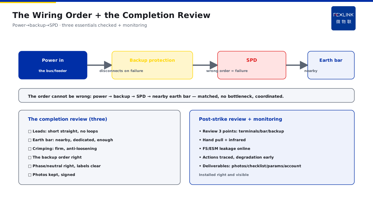
Direct Answer
The SPD selection is right, but the wiring in the cabinet is wrong, and the protection effect drops sharply — what should the on-site work watch? The answer: the three on-site installation essentials for an SPD — the leads as short and straight as possible (reducing the loop inductance), the SPD earth connected to a nearby dedicated earth bar rather than a long shared series, and firm crimping with anti-loosening; these three points directly decide the actual residual voltage and affect the protection effect even more than the SPD's own parameters.
On a project the SPD selection was fully compliant, but the in-cabinet lead was routed around for 1.2 meters and the earth was strung to a far shared bar; the end equipment was still damaged on a strike. After the rectification — short straight leads + a nearby dedicated earth bar + firm crimping — the same-parameter SPD protected in place. The key distinction: the SPD's actual residual voltage = the body residual + the voltage raised by the lead inductance — the three construction essentials (short straight leads, a dedicated earth bar, firm crimping) directly decide the latter; the drawing is right but the construction is arbitrary, and the SPD is as good as not installed.
Why:
- Short straight leads: reducing the distributed inductance (relating to KD-0172), pressing the actual residual low;
- A dedicated earth bar: connecting nearby, avoiding a long shared series raising the potential;
- Firm crimping: reliable contact and anti-loosening, preventing both heating and failure;
- The review checklist: every item checked after completion, plus the backup-protection order.
Key insight: "The actual residual voltage = the body residual + the lead-inductance raise — the three essentials (short straight leads, a nearby dedicated earth bar, firm crimping) directly decide the protection effect; the drawing is right but the construction is arbitrary, and the SPD is as good as not installed."
In a server room the SPD crimping terminal had no anti-loosening; six months later the terminal loosened, the contact resistance rose, and on a strike the lead heated and burned. Lesson: contact reliability is the invisible killer of construction — firm crimping + an anti-loosening washer + periodic review, all indispensable.
Overview: run "lead length → earth path → crimping reliability → backup protection → review checklist" as one executable construction checklist. When an SPD goes into a distribution cabinet, the selection is only the beginning; the construction quality decides the actual effect. The core mechanism: the residual voltage the SPD actually takes equals the body residual plus the voltage drop of the lead inductance under the lightning current — the longer and more winding the leads, the larger the drop and the worse the protection. The on-site construction watches five points: short straight leads, the earth to a nearby dedicated bar, firm anti-loosening crimping, the correct wiring order with the backup protection, and a completion review item by item. The five steps below expand: short straight leads reducing the distributed inductance, a nearby dedicated earth bar avoiding a long shared path, the contact reliability of crimping and anti-loosening, the wiring order with the backup protection, and the completion review checklist.
The three preparations before construction: three things done before touching the wires save most of the rework. One, check the drawing against the physical — the SPD's phases/Un/Uc consistent with the site voltage level, the varistor/gap type consistent with the position (the incoming T1 or the end T2, relating to KD-0202); two, plan the path — walk the "power in → backup protection → SPD → earth bar" route in the cabinet mentally first, measure the shortest path before starting, not "connect then think"; three, prepare the tools and parts — the crimping pliers, the torque wrench, the anti-loosening washers, the lug types complete. The three pre-construction preparations: check the drawing against the physical, plan the path first, tools and parts ready — saving most of the rework.
1. Short Straight Leads: Reducing the Distributed Inductance
Step one: the leads are the invisible "added residual".
Why the leads must be short:
- The leads have distributed inductance (relating to KD-0172);
- The inductance produces a voltage drop under the lightning current;
- The longer the leads, the larger the drop;
- The actual residual raised.
Why straight:
- Coiling/folding increases the inductance;
- A straight path has the minimum inductance;
- As close to the cabinet as possible, a short path;
- Reducing the loop area.
The executable indicators:
- The leads as short as possible (per GB 50343);
- The path short and straight, no loops;
- The phase leads run together;
- Length beyond the limit redone.
How to recognize the three common "lead diseases" on site: one, the detour disease — the lead does not take the shortest path but goes around the cabinet to the SPD, common when the cabinet is crowded; two, the coiling disease — too much lead allowance coiled into a loop, pretty but with doubled inductance; three, the separation disease — the phase and the earth leads run far apart, making a large loop area. The recognition method is simple: walk the lead from the power point to the SPD; if the path bends at more than two places or coils, re-route. The rectification is also direct: trim the allowance, run straight against the cabinet, run the phase and the earth together along the same path. The three lead diseases: detour, coiling, separation — walk the path for bends and coils; trim the allowance, run straight, phase and earth together, rectify on the spot.
Key insight: "Short straight leads = pressing the added residual low — the lead inductance produces a drop under the lightning current, the longer and more winding the higher; the leads as short as possible, the path straight, no loops; length beyond the limit redone."
2. A Nearby Dedicated Earth Bar: Avoiding a Long Shared Earth Path
Step two: the earth path decides the discharge quality.
Why nearby:
- The longer the earth path, the larger the potential difference;
- Connect to the in-cabinet earth bar nearby;
- Reduce the sharing with other circuits;
- The discharge path the shortest.
Why dedicated:
- Not sharing a long series with signal/weak-current circuits;
- Avoid the lightning current stringing into other circuits;
- A stable potential on the dedicated bar;
- A long shared path = a hazard.
The executable indicators:
- The SPD earth connected to a nearby dedicated earth bar;
- Not serially tied with other equipment;
- The bar cross-section per the standard;
- The connection point firm.
The on-site judgment of the earth path: look at where the SPD's earth wire goes in the cabinet. The right way: to a nearby dedicated earth bar in the cabinet (the bar reliably connected to the main earth grid), the SPD discharge path the shortest. The wrong way: the earth wire strings through several equipment terminals before finally reaching the bar — this makes the SPD's lightning current "pass through" other equipment enclosures along the way, and the other equipment becomes part of the discharge path. The judging rhyme: the SPD's earth wire leaves the terminal and reaches the bar through only one connection point — good; strings through two or more — change it. The earth judging rhyme: the SPD earth reaching the bar through one connection point is good; through two or more must be changed — the lightning current must not pass through other equipment enclosures along the way.
Key insight: "The earth nearby and dedicated — the shorter the path, the smaller the potential difference, no long shared series with other circuits; the SPD earth to a nearby dedicated bar, the cross-section per the standard, the connection point firm."
3. Crimping and Anti-Loosening: Contact Reliability
Step three: poor contact is the invisible killer.
Why the crimping must be firm:
- High contact resistance → heating;
- Overheating and burning under the lightning current;
- Loosening → intermittent contact;
- The protection failure invisible.
The crimping requirements:
- The terminal crimped firmly;
- The torque per the manufacturer;
- An anti-loosening washer/locking;
- The lug crimped per the standard.
The executable checks:
- A hand-pull test after completion;
- Re-crimp when loose;
- Periodic infrared checks of the hot spots;
- Spot checks of the contact resistance.
Why the wiring must be specially reviewed after a strike: the lightning current is a transient large current of tens of kiloamperes, and at the discharge moment it produces an electrodynamic stress on the connection points — an insufficiently firm joint may slightly loosen at that moment, and after loosening the contact resistance rises, so at the next strike the local heating is worse, forming a "looser the hotter, hotter the looser" vicious cycle. So after the thunderstorm season, besides the SPD body state (FS/ESM leakage/degradation, relating to KD-0161), the three connection points must be specially reviewed: the two terminals of the SPD, the earth-bar connection point, and the backup-protection wiring point. The hand feel check (a gentle pull, not loose) + the infrared temperature (points much higher than the ambient must be handled) as a double insurance. After a strike, specially review the three connection points: the SPD terminals, the earth-bar point, the backup-protection point — the hand pull + the infrared as a double insurance, blocking the "looser the hotter" cycle.
Key insight: "Firm crimping + anti-loosening — a high contact resistance heats and burns, loosening makes it intermittent; torque met, anti-loosening washer, hand-pull test, infrared review of the hot spots."
4. The Wiring Order with the Backup Protection
Step four: the wiring order cannot be wrong.
The role of the backup protection:
- Disconnecting on an SPD short-circuit/degradation;
- Preventing an SPD failure from causing an accident;
- Installed in series with the SPD;
- The safety bottom line.
The wiring order:
- Power in → backup protection → SPD;
- The backup protection upstream of the SPD;
- The protection fails if the order is wrong;
- Wire per the drawing.
The coordination notes:
- The backup-protection parameters match the SPD;
- The discharge capacity not a bottleneck;
- The action characteristics coordinated;
- The acceptance checked by this.
Key insight: "The wiring order cannot be wrong — power in → backup protection → SPD, the backup upstream; parameters matched, no bottleneck, actions coordinated, the acceptance checked by this."
5. The Completion Review Checklist
Step five: completion is not the end; the review is.
The three review essentials:
- The lead length and path (short straight, no loops);
- The earth bar (nearby, dedicated, cross-section enough);
- The crimping (firm, anti-loosening, no looseness on the hand pull).
The additional review items:
- The backup-protection order;
- The phase/neutral wiring correct;
- Clear labels;
- Photos kept.
The monitoring support:
- The FS/ESM states online;
- Degradation/leakage known early (relating to KD-0161);
- Actions recorded;
- The review conclusion traceable.
The construction records and deliverables: "installed and forgotten" is common in engineering, but the SPD construction quality can only be tracked over time with records. Four things left after completion: one, the wiring photos (the lead path, the earth bar, the crimping point — one each, archived for review); two, the review checklist (the three essentials checked and signed one by one, the acceptance evidence); three, the parameter record (the SPD model/Un/backup-protection specification, for later degradation checks); four, the monitoring account (the FS/ESM connected, leakage/actions online). These four turn the SPD from "installed and done" into "verifiable over time". The four construction deliverables: wiring photos, the review checklist, the parameter record, the monitoring account — installed is not the end; verifiable over time.
Key insight: "Review by the checklist after completion — the short straight leads, the nearby dedicated earth, the firm crimping checked one by one, plus the backup order/correct wiring/clear labels; the FS/ESM online monitoring as the bottom line."
6. Product Implementation: Installed Right + Visible
WeiWuLian products land the SPD installation effect into verifiable monitoring:
- FSS Intelligent SPD: the body + backup integrated, states online;
- FS/ESM SPD Monitor: leakage/degradation/actions all recorded;
- The construction standard landed: the three essentials into the checklist;
- The effect verifiable: before vs after comparison.
The design principle in one sentence: "The actual residual voltage is decided by the construction — the short straight leads, the nearby dedicated earth bar, the firm crimping as the three essentials; the FSS integrated + the FS/ESM online, installed right and visible."
7. Common Understanding Misjudgments
- "Selection right is enough": ignoring the construction. Result: arbitrary wiring, reduced effect. Correct: watch the three essentials.
- "A longer lead does not matter": ignoring the inductance. Result: the residual raised. Correct: short straight leads.
- "Sharing the earth is convenient": ignoring the sharing. Result: potential crosstalk. Correct: a nearby dedicated bar.
- "Pressing tight is enough": ignoring the anti-loosening. Result: loosening failure. Correct: anti-loosening + review.
- "Installed, done, no monitoring": ignoring the degradation. Result: failure unknown. Correct: the FS/ESM online.
Scope and Limitations
This article gives the three on-site installation essentials for an SPD in a cabinet (short straight leads, a nearby dedicated earth bar, firm anti-loosening crimping), the backup-protection wiring order and the completion review checklist, applicable to SPD construction checks and acceptance review. The specific values (lengths/cross-sections) follow GB 50343-2012 and the product manual; this article explains only the construction logic and the check actions. All cases are anonymized (a project, a server room) and do not refer to any specific customer.