 微物联研究院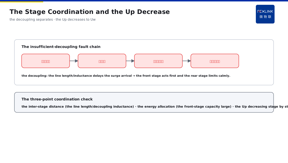
Direct Answer
Why can the SPD not be installed at only one stage at the main distribution board, but must be staged? The answer: set the SPDs stage by stage along the LPZ boundaries — T1 (Class I, 10/350 µs) at the main incoming line takes the high energy of the direct strike, T2 (Class II, 8/20 µs) at the sub-distribution board further limits the voltage, and T3 (fine protection) at the sensitive equipment end presses the residual voltage below the equipment withstand; the front stage discharges the energy and the rear stage limits the voltage, achieving the step-down stage by stage through the energy coordination and the decoupling impedance.
At a factory, only one T1 SPD was installed at the main distribution board, with neither the sub-distribution boards nor the equipment ends protected; after a strike, the residual voltage at the equipment end still exceeded 1500 V and the PLC modules failed in batches. After the T2 and T3 were added per the LPZ grading, under the same strike the residual voltage at the equipment end was pressed below 800 V. The key distinction: the SPD is not "one is enough" — T1 discharges the high energy of the direct strike, T2 further limits the voltage, and T3 presses the residual voltage below the equipment withstand; the front stage discharges the energy and the rear stage limits the voltage, achieving the step-down stage by stage through the energy coordination and the decoupling.
Why:
- T1 (10/350 µs): at the main incoming line, taking the high energy of the direct strike;
- T2 (8/20 µs): at the sub-distribution board, further limiting the voltage;
- T3 (fine protection): at the equipment end, pressing the residual voltage below Uw;
- The coordination logic: the front stage discharges the energy, the rear stage limits the voltage, and the decoupling separates the stages.
Key insight: "The SPD staging is not stacking the quantity — T1 discharges the high energy of the direct strike, T2 further limits the voltage, and T3 presses the residual voltage below the equipment withstand; the front stage discharges the energy, the rear stage limits the voltage, the decoupling impedance separates the stages, and the Up decreases stage by stage."
At an office building, the SPD was installed at only one stage at the incoming line, with no protection at the sub-distribution boards or the equipment ends; after a strike, T1 was not damaged but the equipment still failed. The investigation found that the residual voltage barely dropped from the incoming line to the equipment end, and the equipment withstand was insufficient. After the T2 and T3 were added, the residual voltage decreased stage by stage and the equipment no longer failed. Lesson: the residual voltage decreasing stage by stage is the coordination — with only one stage, the residual voltage cannot be pressed down and the equipment still fails; the staging plus the decoupling is complete.
Overview: run "how the three-stage SPDs are placed at the LPZ boundaries → how much energy 10/350 differs from 8/20 → how the stages coordinate and decouple → how the Up decreases to Uw" as one coordination principle. The SPD is not "one is enough". The lightning current entering from the LPZ0 zone decays in energy stage by stage and is pressed in voltage stage by stage: T1 at the main incoming line takes the high energy of the direct strike, T2 at the sub-distribution board further limits the voltage, and T3 at the sensitive equipment end presses the residual voltage below the equipment withstand. The front stage discharges the energy and the rear stage limits the voltage, achieving the step-down stage by stage through the energy coordination and the decoupling impedance. The four layers are unfolded below.
A "relay race" analogy: think of the three-stage SPDs as a relay race. T1 is the first leg — at the main incoming line, it first holds the "boulder" of the direct strike and discharges most of the energy; T2 is the second leg — at the sub-distribution board, it presses the remaining surge down one more notch; T3 is the sprint leg — at the equipment end, it presses the residual voltage below the equipment withstand. The three legs are separated by the "track" of the decoupling, letting the front leg finish first and the rear leg exert after; with one leg missing or the track too short, the surge "skips the stage" and hits the equipment directly. The relay analogy: T1 holds the boulder (discharging the energy) → T2 presses one notch (limiting the voltage) → T3 sprints (pressing below Uw); the decoupling is the track separating the stages — missing a leg or a too-short track skips the stage.
1. The Three-Stage SPDs: How to Place Them at the LPZ Boundaries
Step one: first look at the positions of the three-stage SPDs at the lightning-protection-zone boundaries.
T1 (the LPZ0→1 boundary):
- Installed at the main incoming line;
- Taking the direct-strike current;
- The waveform 10/350 µs;
- Discharging most of the energy.
T2 (the LPZ1→2 boundary):
- Installed at the sub-distribution board;
- Taking the induced and the remaining energy;
- The waveform 8/20 µs;
- Further limiting the voltage.
T3 (the equipment end):
- Installed at the sensitive equipment port;
- Pressing the residual voltage below Uw;
- The fine protection;
- Matched with the equipment withstand.
Key insight: "The three stages are placed along the LPZ boundaries — T1 at the main incoming line (LPZ0→1) takes the direct strike, T2 at the sub-distribution board (LPZ1→2) limits the voltage, and T3 at the equipment end presses the residual voltage below Uw — each stage manages one section, and the residual voltage decreases stage by stage."
2. The Waveform Difference: How Much 10/350 Differs from 8/20
Step two: why does T1 need 10/350 and T2 use 8/20? The waveform decides the energy.
10/350 µs (T1):
- Simulating the direct-strike current;
- Rising 10 µs, decaying 350 µs;
- Large single-shot energy;
- Testing the discharge capability.
8/20 µs (T2):
- Simulating the induced-strike current;
- Rising 8 µs, decaying 20 µs;
- A "thinner" waveform;
- Testing the voltage-limiting speed.
The energy difference:
- The energy of 10/350 is far larger than that of 8/20;
- Using the wrong waveform damages the SPD;
- T1 discharges and T2 limits;
- Each does its own job.
Key insight: "The waveform decides the duty — 10/350 simulates the direct strike with large single-shot energy (T1 discharges), and 8/20 simulates the induced strike with a thinner waveform (T2 limits); using the wrong waveform damages the SPD, and only when each does its own job is it safe."
3. The Stage Coordination: How to Decouple
Step three: how do the multi-stage SPDs coordinate? The decoupling impedance separates the stages.
The energy coordination:
- The front stage discharges most of the energy;
- The rear stage takes the rest and limits the voltage;
- Reasonably allocated between the stages;
- Avoiding the rear-stage overload.
The decoupling principle:
- The line length/inductance decouples between the stages;
- The decoupling impedance delays the surge arrival;
- The front stage acts first;
- The rear stage limits the voltage calmly.
The coordination consequences:
- Insufficient decoupling makes the rear stage act first;
- The backup protection skips the stage;
- The SPD breaks down;
- The line length/inductance per the standard.
Key insight: "The stage coordination relies on the decoupling — the front stage discharges most of the energy and the rear stage takes the rest to limit the voltage; the line length/inductance serves as the decoupling impedance to delay the surge arrival and make the front stage act first; with insufficient decoupling, the rear stage acts first, the stage is skipped and the SPD breaks down."
An on-site way to judge "whether the coordination is in place": for a set of staged SPD layouts, judge the coordination by three points. One, "the inter-stage distance" — whether the line length between T1 and T2 is enough (usually keep meter-level distance per the standard or add the decoupling inductance); two, "the energy allocation" — the front-stage discharge capacity far larger than the rear, showing that the front stage takes the main discharge; three, "the Up chain" — the Up of each stage decreases stage by stage from the incoming line to the equipment end, with the chain end below the equipment Uw and with a margin. With the three points valid, the coordination is in place. The three-point coordination check: whether the inter-stage distance is enough (the line length/decoupling inductance), whether the energy allocation is right (the front-stage capacity large), and whether the Up decreases stage by stage (the chain end below Uw with a margin).
The "typical fault chain" of insufficient decoupling: the staged SPD most fears the insufficient decoupling, and the fault appears along a chain. Step one, the rear stage acts first — with the inter-stage line length too short, the surge reaches the front and rear stages simultaneously and the rear T2 discharges first; step two, the rear stage overloads — T2 takes the energy that T1 should have taken and the discharge capacity is exceeded; step three, the backup protection skips the stage — the fuse/circuit breaker of T2 trips first and cuts off the whole stage protection; step four, the equipment loses the protection — after the SPD exits, the surge pours directly into the equipment. These four links form the complete fault chain of "insufficient decoupling → stage skipped → SPD breakdown → equipment damage". The insufficient-decoupling fault chain: the rear stage acts first → the rear stage overloads → the backup protection skips the stage → the equipment loses the protection — the four steps link into the stage skip and the equipment damage.
4. The Up Decrease: How to Press Below Uw
Step four: the landing point of the step-down is the equipment-withstand Uw matching.
The Up decreasing stage by stage:
- The T1 residual voltage higher;
- T2 further pressing it down;
- T3 pressing to the lowest;
- The chain-end Up below Uw.
The Uw matching:
- The equipment withstand Uw is the bottom line;
- The chain-end Up must be below Uw;
- Keep a margin above 20%;
- With a wrong matching, the equipment still fails.
The system completeness:
- T1+T2+T3 forming the chain;
- The decoupling separating the stages;
- The Up decreasing stage by stage;
- The equipment end safe.
Key insight: "The landing point of the step-down is Uw — the T1 residual voltage is higher, T2 presses it down, and T3 presses it to the lowest at the chain end; the chain-end Up must be below the equipment withstand Uw with a margin, and with a wrong matching the equipment still fails."
5. Product Implementation: The Stage Step-Down Made Monitorable
WeiWuLian products bring the stage step-down to the verifiable level:
- FSS intelligent surge protective device: the full T1/T2/T3 series;
- The SPD monitoring: the operation counts/degradation of each stage online;
- The data review: whether the inter-stage coordination fails;
- The loop optimization: the step-down chain continuously verified.
The design principle in one sentence: "The stage step-down and the monitoring close the loop — T1 discharges the energy, T2 limits the voltage, and T3 presses the residual voltage; the FSS full series covers, and the SPD monitoring records the operations and the degradation of each stage, exposing the coordination failure in time."
6. Common Understanding Misjudgments
- "One SPD is enough": wrong. The residual voltage cannot be pressed down and the equipment still fails; the stage step-down is needed.
- "T1 can replace T2": wrong. T1 discharges the energy, its voltage-limiting speed is not as good as T2, and the duties differ.
- "The waveform does not matter": wrong. The energy of 10/350 differs from that of 8/20 by an order of magnitude, and the wrong one damages the SPD.
- "No decoupling is needed between the stages": wrong. With insufficient decoupling, the rear stage acts first, the stage is skipped and the SPD breaks down.
- "The Up being roughly the same is fine": wrong. The chain-end Up must be below Uw with a margin, otherwise the equipment still fails.
Scope and Limitations
This article explains the T1/T2/T3 SPD stage step-down principle along the LPZ boundaries (the LPZ-boundary placement, the waveform energy difference, the stage coordination/decoupling, and the Up-Uw matching), applicable to the staged configuration and the selection judgment. The specific parameter selection and the installation distance follow IEC 61643-11 and GB/T 18802.11; this article explains only the coordination logic. All cases are anonymized (a factory/an office building) and do not refer to any specific customer.