 微物联研究院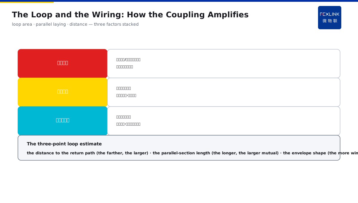
Direct Answer
When the strike point is far from the equipment, yet thousands of volts of surge appear on the wiring, how does this overvoltage "build up"? The answer: the rapidly changing electromagnetic field of the strike induces an electromotive force in the nearby loops — mutual inductance produces a surge between the parallel conductors, electrostatic induction charges the conductor-to-ground capacitance, and the ground-grid potential rise creates a common-mode overvoltage between the equipment at both ends; the longer the conductors, the larger the loop area, and the closer to the strike, the more severe the induced surge.
At a weak-current shaft, a 40-meter unshielded signal line was struck far from the building (the strike point was about 500 m away); after the strike, the switch ports failed in batches, and the measured induced surge on the line exceeded 2000 V. After switching to shielded twisted pair and reducing the loop area, no more port failures occurred under the same kind of strike. The key distinction: the induced overvoltage is not "the lightning coming in" but "induced" by the electromagnetic field on the conductors — mutual coupling produces a surge between the parallel conductors, electrostatic induction charges the conductor to ground, and the ground-potential rise produces a common-mode voltage; the longer the conductors, the larger the loop and the closer to the lightning, the more severe.
Why:
- Mutual coupling: the magnetic field of the parallel-conductor loop induces a voltage;
- Electrostatic induction: the conductor-to-ground capacitance is charged by the electric field;
- Common-mode overvoltage: the ground-grid potential rise is transferred to the equipment at both ends;
- The intensity factors: the longer the conductors, the larger the loop, the closer to the lightning, the more severe.
Key insight: "The induced overvoltage is 'induced' by the electromagnetic field — mutual coupling produces a surge between the parallel conductors, electrostatic induction charges the conductor to ground, and the ground-potential rise produces a common-mode voltage; the length, the loop area and the distance decide the severity."
At a factory, a signal cable and a power cable were laid in the same trough for 30 m; after a distant strike, the acquisition card was damaged. The investigation found that the parallel section of the two cables formed a large mutual-inductance loop, and the induced surge poured into the acquisition card. After separating the cables and adding the shielding, no more damage occurred under the same kind of strike. Lesson: the coupling strength is decided by the wiring — the long parallel distance and the large loop area are the "antenna", and the shielding/twisting/equipotential bonding is the way to cut the coupling.
Overview: run "how the three couplings build the overvoltage on the wiring → how the loop and the wiring amplify → how to cut the coupling → how the SPD handles the remainder" as one mechanism illustration. The strike point is far from the equipment, yet thousands of volts of surge appear on the wiring — this overvoltage is not "the lightning coming in" but "induced" by the rapidly changing electromagnetic field of the strike in the nearby loops. Mutual coupling produces a surge between the parallel conductors, electrostatic induction charges the conductor to ground, and the ground-potential rise produces a common-mode voltage; the longer the conductors, the larger the loop and the closer to the lightning, the more severe. The four layers are unfolded below.
A "transformer" analogy: think of the mutual coupling as an invisible transformer. The strike channel is the "primary winding", the nearby conductor loop is the "secondary winding", and although there is no conductor connection between them, the magnetic field "moves" the energy from the primary to the secondary — the rapidly changing lightning current is the excitation of this transformer, and a voltage is induced in the secondary (the conductor loop). The larger the loop and the tighter the coupling (the longer the parallel section), the larger the "transformer ratio" and the higher the induced voltage. The transformer analogy: the strike channel = the primary winding and the conductor loop = the secondary — the magnetic field moves the energy without contact; the larger the loop and the longer the parallel section, the larger the ratio and the higher the induced voltage.
1. The Three Couplings: How the Overvoltage Builds Up
Step one: first look at how the three coupling mechanisms build the overvoltage on the wiring.
Mutual coupling (the parallel conductors):
- The rapidly changing lightning current produces a magnetic field;
- The parallel-conductor loop cuts the field lines;
- An electromotive force is induced;
- The longer the parallel section, the larger the surge.
Electrostatic induction (to ground):
- The thundercloud/strike field acts on the conductor;
- The conductor-to-ground capacitance is charged;
- A voltage to ground appears;
- The stronger the field, the higher the voltage.
Common-mode overvoltage (the ground-potential rise):
- The lightning current entering the ground raises the grid potential;
- The ground potentials of the equipment at both ends differ;
- A common-mode voltage appears between the equipment;
- The insulation is damaged.
Key insight: "The three couplings — mutual coupling induces an emf between the parallel conductors (the longer the parallel section, the larger it is), electrostatic induction charges the conductor to ground (the stronger the field, the higher it is), and the ground-potential rise produces a common-mode voltage between the equipment at both ends (dangerous when the potentials differ)."
2. The Loop and the Wiring: How They Amplify
Step two: under the same strike, why are some lines induced and others not? The wiring decides the coupling strength.
The loop area:
- The conductor with the ground/shield forms a loop;
- The larger the loop area, the larger the induction;
- Reducing the area reduces the coupling;
- Twisted pair greatly shrinks the loop.
The wiring way:
- The parallel laying has the largest mutual inductance;
- Near the ground/shield, the loop is small;
- In the same trough with the power cable, the coupling is strong;
- Separate troughs/farther away reduce the coupling.
The distance factor:
- The closer to the strike, the stronger the field;
- The larger the strike current amplitude, the stronger the field;
- The faster the change rate, the stronger the induction;
- The three factors stack to decide the severity.
Key insight: "The coupling strength is decided by the wiring — the larger the loop area, the larger the induction (the twisted pair shrinks the loop), the parallel/same-trough has the largest mutual inductance (separate and keep away to reduce it), and the closer to the lightning/the larger the current/the faster the change, the more severe — the three factors stack to decide the severity."
An on-site way to "estimate" the loop area: when wiring, the loop area does not need an exact calculation; look at three points. One, "the line and the return path" — the farther the signal line from its return path (the ground/shield/adjacent line), the larger the loop; two, "the parallel-section length" — the longer the two lines run side by side, the larger the mutual inductance; three, "the envelope shape" — the more the line winds and the larger the area it envelops, the larger the coupling. With the three points roughly judged, change the wiring when the loop is large. The three-point loop estimate: the distance between the line and the return path (the farther, the larger), the parallel-section length (the longer, the larger mutual inductance), and the envelope shape (the more winding, the larger the area) — change the wiring when the loop is judged large.
3. How to Cut the Coupling
Step three: the shielding, the twisting and the equipotential bonding are the three tools to cut the coupling.
The shielding:
- The shield layer forms a low-resistance loop;
- The magnetic coupling is short-circuited and diverted;
- The shield single-end/double-end grounded per the standard;
- The shield continuity is the key.
The twisting:
- The adjacent twist loops have opposite directions;
- The induction cancels each other;
- The first choice for the signal lines;
- More stable when combined with the shield.
The equipotential bonding:
- The potentials of the equipment at both ends are consistent;
- The common-mode voltage is flattened;
- Combined with the shield;
- The potential difference between the equipment is eliminated.
Key insight: "The three tools to cut the coupling — the shielding (the shield layer diverts the magnetic field through the low-resistance loop), the twisting (the adjacent twist loops cancel the induction), and the equipotential bonding (the consistent potentials at both ends flatten the common mode); with the three combined, the induced surge drops greatly."
The two ways of shield grounding and the consequences: the shield grounding is not arbitrary. The signal-line shield is usually single-end grounded — one end connected to the reference ground, to avoid the ground-potential difference between the two ends forming a loop current in the shield and introducing interference instead; the power/high-frequency cases may be double-end grounded per the standard — providing the low-resistance discharge path. The typical consequence of the wrong connection: the double-end grounding forms a ground loop current and the shield becomes the "interference antenna"; with the wrong single-end position, the shield hangs idle and has no effect. The shield grounding: the signal line is usually single-end grounded (against the ground loop current), and the power/high-frequency cases are double-end per the standard (low-resistance discharge) — the wrong connection becomes the ground-loop antenna, and the floating one fails.
4. How the SPD Handles the Remainder
Step four: when the coupling cannot be cut cleanly, the SPD discharges the remainder at the port.
The SPD role:
- Limiting the overvoltage at the port;
- Discharging the surge when it conducts along the shield/line;
- Protecting the equipment port;
- Complementary with the shield and the equipotential bonding.
The selection basis:
- Selecting the discharge capacity by the induction strength;
- Grading by the LPZ zones;
- Installed close to the port;
- Combined with the monitoring.
The system cooperation:
- The shield/twisting reduces the coupling;
- The SPD discharges the remaining surge;
- The equipotential bonding eliminates the common mode;
- The three-layer cooperation makes the system complete.
Key insight: "The SPD handles the remainder at the port — the shield/twisting reduces the coupling, the SPD discharges the remaining surge, and the equipotential bonding eliminates the common mode; select the discharge capacity by the induction strength, grade by the LPZ and install close to the port, and the three-layer cooperation makes the system complete."
A three-step way to "locate" the induced-lightning damage: when the equipment is damaged by a distant strike, locate the coupling path in three steps. Step one, look at "whether there is a parallel section" — how far the damaged line runs parallel with the power/other cables, and the parallel section is the high-frequency mutual-coupling area; step two, look at "whether the loop is large" — the area enveloped by the line and the return path, the larger the easier to be induced; step three, look at "whether the SPD is in place" — whether the port SPD discharge capacity matches and the installation is close to the port. After the three-step location, change the wiring, add the shield, and add the SPD — choose one or combine. The three-step location: look at the parallel section (the mutual-coupling high-frequency area) → look at the loop area (the larger, the easier to be induced) → look at the SPD in place (the discharge capacity/the position) — after the location, change the wiring/add the shield/add the SPD.
5. Product Implementation: The Coupling Protection Made Verifiable
WeiWuLian products bring the induced-lightning protection to the verifiable level:
- FSS intelligent surge protective device: the port surge discharge and the degradation monitoring;
- The SPD monitoring: the operation count/degradation online;
- The data review: the surge events compared with the wiring improvements;
- The loop optimization: the protection effect continuously verified.
The design principle in one sentence: "The wiring reduces the coupling, the SPD handles the remainder, and the monitoring verifies the effect — the twisting/shield/equipotential bonding reduces the induction, the FSS discharges at the port, and the SPD monitoring records the operations and the degradation, closing the data loop of the induced-lightning protection."
6. Common Understanding Misjudgments
- "Far from the strike, nothing happens": wrong. A strike hundreds of meters away still induces a surge on the long conductors.
- "The overvoltage is the lightning current coming in through the line": incomplete. A distant strike is mainly the electromagnetic-field induction, not the direct invasion.
- "With the SPD, the wiring does not matter": wrong. The SPD handles the remainder but the coupling still exists; the wiring reducing the coupling is the root treatment.
- "The shield layer can be grounded arbitrarily": wrong. The single-end/double-end grounding follows the standard; the wrong connection introduces the interference instead.
- "The loop area does not matter": wrong. The larger the loop, the larger the induction; it must be controlled at the wiring time.
Scope and Limitations
This article illustrates the LEMP induced-overvoltage coupling mechanism (the three couplings of mutual/electrostatic/common-mode, the loop-and-wiring amplification, the cutting tools, and the SPD remainder), applicable to the SPD configuration and the shield-design judgment. The specific quantitative calculation of the induced voltage follows GB 50343-2012 and the relevant electromagnetic-compatibility standards; this article explains only the physical mechanism. All cases are anonymized (a weak-current shaft/a factory) and do not refer to any specific customer.