 微物联研究院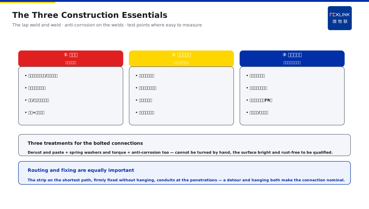
Direct Answer
The bonding and earth-main drawings look good, but how are the on-site welding, anti-corrosion and test points done to be qualified? The answer: the field work on bonding bars and earth mains must implement three points — the lap-weld length and a full weld, anti-corrosion treatment on the welds, and earth test points reserved where easy to measure; unreliable connections are the main on-site cause of bonding failure, and the acceptance should check these three points item by item rather than looking only at the drawing.
On a project the bonding drawings were complete, but on site the lap welds were only tacked in two or three spots with cold welds, and no anti-corrosion was applied to the welds; a year later the connection points rusted, the bonding was "visually connected but not actually connected", and on a strike the potential difference between equipment hurt someone. After the rectification — full welds + anti-corrosion + reserved test points — the re-measurement passed. The key distinction: the main on-site cause of bonding failure is an unreliable connection — the lap-weld length and weld, the anti-corrosion on the welds, and the reserved test points directly decide "connected or not"; the acceptance checks these three item by item, not just the drawing.
Why:
- The lap weld: the length and the weld meet the standard, no cold welds;
- Anti-corrosion: rust on the welds is the long-term failure source;
- The test points: reserved where easy to measure, re-measurable and acceptable;
- The on-site spot checks: the connection reliability proven by measurement.
Key insight: "An unreliable connection is the main on-site cause of bonding failure — the lap-weld length/weld, the weld anti-corrosion and the reserved test points checked one by one; not just the drawing."
At a park the earth-main welds had no anti-corrosion; three years later the welds rusted over a large area and the earth-resistance readings rose year by year. Lesson: anti-corrosion is not an option — without it on the welds, the connection eventually fails, and the bonding goes from "connected" to "not connected".
Overview: run "lap weld → anti-corrosion → test points → spot checks → acceptance evidence" as one executable acceptance sheet. For bonding bars and earth mains, the drawing is only the beginning; the on-site connection quality decides everything. An unreliable connection — cold welds, rust, no test points — is the most common on-site cause of bonding failure, and it often only exposes itself at a strike or a fault. The work and acceptance watch five points: the lap-weld length and a full weld, anti-corrosion on the welds, the reserved positions of the test points, the on-site spot checks of the connection reliability, and the measured acceptance with evidence. The five steps below expand: the lap-weld length and weld requirements, anti-corrosion on the welds and connections, the reserved positions of the test points, the on-site spot checks of the connection reliability, and the measured acceptance with evidence.
The material and tool checks before construction: check three things before starting to avoid rework. One, the material — the flat/round steel specifications, the galvanized layer, the length consistent with the design, the strip width and thickness meeting the standard; two, the welding conditions — the welder current adjustable, the electrode type matched, the operator certified, no welding in bad weather (rain/snow/wind); three, the measuring tools — an earth-resistance tester, a multimeter and a tape on site, measuring while welding. A bonding bar with unqualified material is an ineffective project even when welded well. The three pre-construction checks: the material specifications and the galvanized layer, the welding conditions and the certified operator, the measuring tools on site — with unqualified material, even good welding is an ineffective project.
1. The Lap-Weld Length and Weld Requirements
Step one: the weld is the "lifeline" of the bonding.
The lap-weld length:
- The flat-steel lap length per the standard (≥ twice the width, etc.);
- The round-steel lap by the diameter multiple;
- Insufficient length = insufficient connection area;
- The current path restricted.
The weld requirements:
- A full weld, no cold welds;
- Three-side/two-side welding per the standard;
- No slag, no pores;
- A smooth transition at the weld.
Why tack welding is not acceptable:
- A small contact area;
- Local overheating under the lightning current;
- Insufficient mechanical strength;
- The bonding is as good as not done.
Key insight: "The weld is the lifeline — the lap length per the standard (each multiple for flat/round), a full weld without cold welds; a tack weld has a small contact area and overheats under the lightning current — as good as not done."
The routing and fixing of the strip: besides the weld itself, the routing of the bonding strip also affects the effect. One, the strip follows the shortest path connecting the equipment/metal members, no detours (a detour = more impedance, a larger potential difference under the lightning current); two, the strip is fixed firmly, with even spacing, not hanging or shaking (a hanging strip may swing and loosen under the electrodynamic force of the lightning current); three, protective conduits at the wall/floor penetrations to avoid mechanical damage. The routing and fixing affect "connected or not" just as much as the weld. Routing and fixing are equally important: the strip on the shortest path, firmly fixed without hanging, conduits at the penetrations — a detour and hanging both make the connection nominal.
2. Anti-Corrosion on the Welds and Connections
Step two: anti-corrosion decides the long-term reliability.
Why anti-corrosion:
- The welds are the corrosion weak points;
- Rust → contact resistance rising;
- The connection failing gradually;
- The bonding going from "connected" to "not connected".
The anti-corrosion practice:
- Derusting after welding;
- Anti-corrosion paint/bituminous paint;
- Enhanced anti-corrosion for the buried parts;
- Anti-rust on the connecting bolts.
The acceptance checks:
- The anti-corrosion coverage complete on the welds;
- No bare rust points;
- The buried connections treated in place;
- Periodic re-coating.
Key insight: "Anti-corrosion decides the long-term reliability — the welds are the corrosion weak points and rust raises the contact resistance; derust and coat after welding, strengthen the buried parts, check the coverage complete at the acceptance."
The handling of bolted connections and detachable points: not every connection must be welded — positions that need to be opened for testing or maintenance later (e.g. test points, disconnecting clamps) use bolts, but three things must be handled: one, derust the contact surfaces and apply a conductive paste for a low contact resistance; two, add spring washers against loosening, the bolt torque up to the standard; three, the bolted connections are also protected against corrosion. The bolted-connection checks: cannot be turned by hand, the contact surface bright and rust-free, the pressed surfaces fitting. Three treatments for the bolted connections: derust the surfaces and apply a conductive paste, spring washers against loosening, anti-corrosion at the connections — cannot be turned by hand, the surface bright and rust-free to be qualified.
3. The Reserved Positions of the Test Points
Step three: what cannot be measured cannot be verified.
Why test points:
- Bonding/earthing must be measurable;
- Without a test point, re-measurement is impossible;
- No measured basis for the acceptance;
- No entry point for later maintenance.
The test-point requirements:
- Reserved where easy to measure;
- A visible position with labels;
- The earth resistance measurable (relating to FR);
- The disconnecting/test clamp per the standard.
The position selection:
- Both ends of the mains and the branches;
- At the building entrances;
- Near important equipment;
- Reachable by the measuring tools.
Key insight: "What cannot be measured cannot be verified — test points reserved where easy to measure, labelled, the earth resistance measurable (relating to FR); set at both ends of the mains, the building entrances and near important equipment."
4. The On-Site Spot Checks of the Connection Reliability
Step four: proven by measurement.
The spot-check methods:
- Hand pull/tap check of the welds;
- A multimeter for the connection resistance;
- An earth-resistance tester for the reading;
- The connection points gone through one by one.
The common disqualifications:
- Cold welds/slag;
- Missing anti-corrosion and rust;
- Missing test points;
- Loose connecting bolts.
The spot-check priorities:
- All main connection points covered;
- The branch points sampled;
- The hidden work verified before covering;
- Disqualifications reworked on the spot.
The four specific actions of the spot check: a spot check is not "a glance" but four repeatable actions. One, the tap — tap the weld lightly with a small hammer, judging a cold weld by the sound (a cold weld sounds dull, a solid one crisp); two, the pull — apply a moderate pull to the strip and the terminals, looking for looseness and displacement; three, the measure — measure the connection-point resistance with a multimeter/earth-resistance tester against the qualified value; four, the look — visually check the rust and the coverage. Go through the four actions in the "tap → pull → measure → look" order, every main point, the branch points sampled by ratio. The four spot-check actions: tap (the cold-weld sound) → pull (the looseness) → measure (against the qualified value) → look (the rust) — all main points, the branches sampled by ratio.
Key insight: "Proven by measurement — tap/pull check the welds, a multimeter measures the connection resistance, an earth-resistance tester takes the reading; cold welds, rust, missing test points and loose bolts are all disqualifications."
5. The Measured Acceptance with Evidence
Step five: the acceptance must leave evidence.
The measured contents:
- The lap lengths measured against the standard;
- The welds by sight and tap;
- The anti-corrosion coverage checked;
- The earth resistance measured and recorded.
The evidence requirements:
- The measured data recorded;
- Photos kept (welds/anti-corrosion/test points);
- Photos of the hidden work before covering;
- The test report archived.
The monitoring support:
- The FR earth-resistance monitor online;
- The earth changes with a trend;
- Degradation found early;
- Cross-verified with the off-line readings.
The "verify first, then cover" of the hidden work: earth mains are mostly buried or cast into concrete, and once hidden they cannot be seen — so the hidden work must be verified with evidence before covering, the easiest step to miss and the most costly. The principle is "verify first, then cover": before backfilling/pouring, photograph the welds, the anti-corrosion layer and the strip routing, measure and record, and only after the supervisor/owner confirms may it be covered. Missing this step, a buried bonding strip with a problem can only be dug out — at a high cost. The hidden work is verified first and covered after: photos + measurement + confirmation before backfilling, covered only when qualified — missing this step, buried problems mean digging it out and redoing.
Key insight: "The acceptance measured with evidence — the lap length/weld/anti-corrosion/earth resistance measured item by item, the data and photos archived; the FR online cross-verified with the off-line readings."
6. Product Implementation: Connection Qualified + Online
WeiWuLian products land the bonding work effect into verifiable monitoring:
- FR Earth-Resistance Monitor: the earth resistance online;
- Test-point integration: the monitor connected to the reserved test points;
- The construction standard landed: the weld/anti-corrosion/test point into the acceptance sheet;
- The data traceable: the trend cross-verified with the off-line.
The design principle in one sentence: "An unreliable connection is the main cause of bonding failure — the lap weld, anti-corrosion and test points accepted one by one; the FR online keeps the earthing always visible and verifiable."
7. Common Understanding Misjudgments
- "The drawing right is enough": ignoring the field. Result: cold welds/rust unknown. Correct: check the three item by item.
- "Tack welding is convenient": ignoring the area. Result: the connection nominal. Correct: full welds.
- "Anti-corrosion can be skipped": ignoring the rust. Result: connected becomes not. Correct: coat after welding.
- "No test points": ignoring the measurement. Result: no re-measurement. Correct: reserve where easy to measure.
- "Installed, done, no monitoring": ignoring the degradation. Result: failure unknown. Correct: the FR online.
Scope and Limitations
This article gives the acceptance points for the field work on bonding bars and earth mains (the lap-weld length and weld, the weld anti-corrosion, the reserved test points, the spot checks, the acceptance evidence), applicable to bonding work acceptance and checks. The specific values (lap lengths/anti-corrosion materials) follow GB 50057-2010 and the related standards; this article explains only the work-acceptance logic and the check actions. All cases are anonymized (a project, a park) and do not refer to any specific customer.